ANASEN: Difference between revisions
| (29 intermediate revisions by the same user not shown) | |||
| Line 1: | Line 1: | ||
'''A'''rray for '''N'''uclear '''A'''strophysics and '''S'''tructure with '''E'''xotic '''N'''uclei ('''ANASEN''') is an active target detector. FSU, LSU, and TAM are joined in the development of the project. | |||
= First Generation = | |||
NIM paper : https://doi.org/10.1016/j.nima.2017.07.030 | |||
PRC paper : https://doi.org/10.1103/PhysRevC.105.055806 | |||
== | = Second Generation = | ||
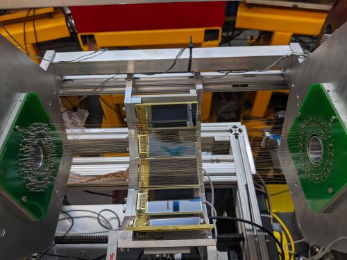
[[File:Section of ANASEN with twisted wire configuration.jpg|500px|thumb|right|Section of ANASEN with twisted wire configuration]] | |||
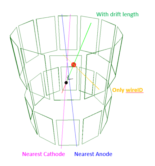
[[File:ANASEN simulation.png|500px|thumb|right|A simulation, showed the Anode wires, the Cathode wites, the SuperX3 Silicon Detector, and QQQ Silicon Detector. The simulation is generated with the analysis and simulation package. The black dot is the reaction vertex, the red dot is the hit position of the superX3, the blue wire is the anode, and the red wire is the cathode. The red line is the track, and the orange line is the reconstructed track only using the SuperX3 position, anode wire ID, and the cathode wire ID.]] | |||
The | The main difference from the 1st generation is the Twisted Anode and Cathode wires. | ||
== | == Gas Handling == | ||
== Basics Geometry == | |||
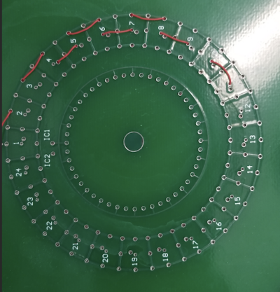
[[File:ANASEN PCB board for wires.png|400px|frameless|none|ANASEN PCB board for wires]] | |||
There are 5 Layers on the radial position of the ANASEN. | |||
= | {|class='wikitable' | ||
! Structure !! Radius [mm] | |||
|- | |||
| ionizing wires || 23 | |||
|- | |||
| Guard wires || 33 | |||
|- | |||
| Anode wires || 38 | |||
|- | |||
| Cathode wires || 43 | |||
|- | |||
| SuperX3 Silicon || 88 | |||
|} | |||
== Twisted Anode and Cathodes == | |||
=== Readout === | |||
== SuperX3 Silicon Detector Array== | |||
[[File:SuperX3 Silicon detector.png|500px|thumb|right|A drawing of SuperX3 silicon detector]] | |||
There are 24 Super-X3 double-sided Silicon detectors on the wall of the ANASEN. They are placed 88 mm away from the beam axis. Each of them has 75 mm X 40 mm sensitive area. Thus, the super-X3 covers a forward and backward angle of 40 deg. | |||
=== | === Readout === | ||
On the front side, each strip has 2 readouts. On the back side, each strip has 1 readout for total energy. | |||
== Tracking for the twisted wire configuration == | |||
. | |||
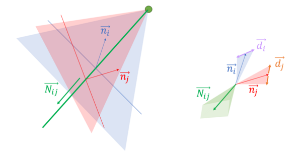
[[File: Illustration of the beam reconstruction of ANASEN in twisted wire configuration.png|600 px|thumb|right|Illustration of the beam reconstruction of ANASEN in twisted wire configuration. (Left) First-order beam reconstruction. (right) uncertainty cone of the beam direction vector.]] | |||
A beam trace consists of 5 parameters: 3 from a point <math> (x_0, y_0, z_0)</math> and 2 from the trace angle <math> (\theta, \phi)</math>. Thus, to reconstruct the beam trace, we need at least 5 pieces of information. | |||
Suppose we know the position on the SuperX3, thus, we have 3 pieces of information <math> \vec{p_0} = (x_0, y_0, z_0)</math>. And We have 2 wires ID. Each wire and the <math>\vec{p_0} </math> will form a plan, the intersection line of the 2 plans will give us the first approximation of the beam trace. | |||
Each wire is constructed from 2 points, let them be <math> \vec{a_i} </math> and <math> \vec{b_i} </math>, where <math> i </math> is the wire ID. The plane formed by the points <math> \vec{p_0}, \vec{a_i}, \vec{b_i} </math> has normal <math> \vec{n_i} = (\vec{p_0} - \vec{a_i}) \times (\vec{p_0} - \vec{b_i}) </math>. The vector for the line intersects between the 2 planes constructed by wire ID <math> i, j</math> and point </math> \vec{p_0}</math> is <math> \vec{N_{ij}} = \vec{n_i} \times \vec{n_j} : (\theta, \phi)</math>. Thus, the beam trace has an equation of <math> \vec{r} = \vec{p_0} + s \vec{N_{ij}} </math>, where <math> s </math> is the coordinate on the line. | |||
=== uncertainty === | |||
Since the beam is not hit directly on the wires, but a distance <math> d_i </math> from the wire. This will rotate the plane on <math> \vec{p_0} </math> along the direction <math> \vec{a_i} - \vec{b_i} </math> by <math> \pm \arctan{d/l} </math>, where <math> l </math> is the perpendicular distance of the point <math> \vec{p_0} </math> and the line. This creates 2 additional planes with normal vectors that are rotated along the line by angle <math> \pm \arctan{d/l} </math>. The 4 additional planes form the uncertainty boundaries of the beam. In other words, the normal vector of the plane has uncertainty <math> \vec{n_i} \pm \vec{d_i} </math> that translates to the beam direction vector <math> \vec{N_{ij}} : (\theta \pm \delta\theta, \phi \pm \delta\phi) </math>. | |||
Additional uncertainty comes from the position of the SuperX3. | |||
== 3D model and Simulation == | |||
A simulation code and 3D model using CERN root can be found https://fsunuc.physics.fsu.edu/git/rtang/ANASEN_analysis/src/branch/master/Armory. | |||
The core is the ANASEN class (ClassAnasen.h). This class contains the geometry (the endpoints of the anode and cathode wire, the edges of the SuperX3). The class can simulate the anode and cathode wire and the position at the SuperX3 with a track. Or, it can deduce the track using the SuperX3, anode, and cathode information. | |||
A Monte Carlo simulation is constructed with the TransferReaction class (ClassTransfer.h). | |||
== DAQ == | |||
The DAQ consists of 7 CAEN V1740D for the SuperX3, 3 CAEN V1735 for the proportional wires. | |||
=== triggering === | |||
Any of the SuperX3 is the trigger. The trig-out of each V1740D will be sent to the input of a Fan-In-Fan-Out (FI-FO), the output of the FIFO will be sent to the TRG-IN of the V1735 digitizers. | |||
=== Clock Zeroing and Time Sync === | |||
one of the V1740D is the master of the reference clock, all other digitizers are slave and use diasy chain CLK-IN CLK-OUT. We a proper PLL firmware settings for the clock, the clock phase of all digitizers would be the same. | |||
To have the same time clock zeroing, we use a Gate generator to generate a clock-zeroing pulse. The pulse will be sent to a FI-FO, and the duplicated clock-zeroing pulse will be sent to all S-IN of the digitizers. | |||
=== FSUDAQ setting === | |||
The [[CAEN_digitizer#FSUDAQ_(using_Qt6) | FSUDAQ]] is used for the DAQ control and data taking. {{Notice | need to fill}} | |||
Latest revision as of 00:44, 27 February 2024
Array for Nuclear Astrophysics and Structure with Exotic Nuclei (ANASEN) is an active target detector. FSU, LSU, and TAM are joined in the development of the project.
First Generation
NIM paper : https://doi.org/10.1016/j.nima.2017.07.030 PRC paper : https://doi.org/10.1103/PhysRevC.105.055806
Second Generation

The main difference from the 1st generation is the Twisted Anode and Cathode wires.
Gas Handling
Basics Geometry
There are 5 Layers on the radial position of the ANASEN.
| Structure | Radius [mm] |
|---|---|
| ionizing wires | 23 |
| Guard wires | 33 |
| Anode wires | 38 |
| Cathode wires | 43 |
| SuperX3 Silicon | 88 |
Twisted Anode and Cathodes
Readout
SuperX3 Silicon Detector Array
There are 24 Super-X3 double-sided Silicon detectors on the wall of the ANASEN. They are placed 88 mm away from the beam axis. Each of them has 75 mm X 40 mm sensitive area. Thus, the super-X3 covers a forward and backward angle of 40 deg.
Readout
On the front side, each strip has 2 readouts. On the back side, each strip has 1 readout for total energy.
Tracking for the twisted wire configuration
A beam trace consists of 5 parameters: 3 from a point and 2 from the trace angle . Thus, to reconstruct the beam trace, we need at least 5 pieces of information.
Suppose we know the position on the SuperX3, thus, we have 3 pieces of information . And We have 2 wires ID. Each wire and the will form a plan, the intersection line of the 2 plans will give us the first approximation of the beam trace.
Each wire is constructed from 2 points, let them be and , where is the wire ID. The plane formed by the points has normal . The vector for the line intersects between the 2 planes constructed by wire ID and point </math> \vec{p_0}</math> is . Thus, the beam trace has an equation of , where is the coordinate on the line.
uncertainty
Since the beam is not hit directly on the wires, but a distance from the wire. This will rotate the plane on along the direction by , where is the perpendicular distance of the point and the line. This creates 2 additional planes with normal vectors that are rotated along the line by angle . The 4 additional planes form the uncertainty boundaries of the beam. In other words, the normal vector of the plane has uncertainty that translates to the beam direction vector .
Additional uncertainty comes from the position of the SuperX3.
3D model and Simulation
A simulation code and 3D model using CERN root can be found https://fsunuc.physics.fsu.edu/git/rtang/ANASEN_analysis/src/branch/master/Armory.
The core is the ANASEN class (ClassAnasen.h). This class contains the geometry (the endpoints of the anode and cathode wire, the edges of the SuperX3). The class can simulate the anode and cathode wire and the position at the SuperX3 with a track. Or, it can deduce the track using the SuperX3, anode, and cathode information.
A Monte Carlo simulation is constructed with the TransferReaction class (ClassTransfer.h).
DAQ
The DAQ consists of 7 CAEN V1740D for the SuperX3, 3 CAEN V1735 for the proportional wires.
triggering
Any of the SuperX3 is the trigger. The trig-out of each V1740D will be sent to the input of a Fan-In-Fan-Out (FI-FO), the output of the FIFO will be sent to the TRG-IN of the V1735 digitizers.
Clock Zeroing and Time Sync
one of the V1740D is the master of the reference clock, all other digitizers are slave and use diasy chain CLK-IN CLK-OUT. We a proper PLL firmware settings for the clock, the clock phase of all digitizers would be the same.
To have the same time clock zeroing, we use a Gate generator to generate a clock-zeroing pulse. The pulse will be sent to a FI-FO, and the duplicated clock-zeroing pulse will be sent to all S-IN of the digitizers.
FSUDAQ setting
The FSUDAQ is used for the DAQ control and data taking.
| need to fill |


