Triton Beam Project: Difference between revisions
| Line 136: | Line 136: | ||
| Output Relays || Pre-accelerator Supply Off<br>Other High-Power Supplies Off || Pre-accelerator Supply Off<br>Other High-Power Supplies Off<br>Both Gate Valves Closed<br>Ionizer Off || Pre-accelerator Supply Off<br>Other High-Power Supplies Off<br>Both Gate Valves Closed<br>Ionizer Off<br>Boiler Off | | Output Relays || Pre-accelerator Supply Off<br>Other High-Power Supplies Off || Pre-accelerator Supply Off<br>Other High-Power Supplies Off<br>Both Gate Valves Closed<br>Ionizer Off || Pre-accelerator Supply Off<br>Other High-Power Supplies Off<br>Both Gate Valves Closed<br>Ionizer Off<br>Boiler Off | ||
|} | |} | ||
= Data Server = | |||
= Contact = | = Contact = | ||
Revision as of 13:09, 22 March 2024
The Triton Beam Project is aiming to establish a triton-beam capability for the FSU accelerator. Its main component is a dedicated injector with a Multi-Cathode Source of Negative Ions by Cesium Sputtering (Multi-SNICS), which will provide triton beams from tritium-loaded titanium cathodes.
Triton Injector
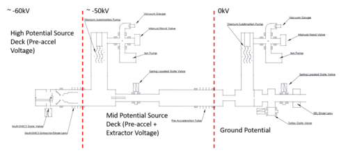
The Triton Injector has components located at three different potentials with different systems:
Ground potential
- Vacuum pumps: Titanium-Sublimation Pump (TSP) 2, Ion-getter pump (IGP)2, Turbo Pump, Roughing pump
- Vacuum instrumentation: Ion-gauge, 2 TC, creating "Good vacuum 2" condition
- Preaccelerator HV(-55 kV) supply
- Fumehood Activity Monitor
- Source Cooling
- Interlock Controller
-55 kV potential
- Vacuum pumps: TSP 1, IGP 1
- Vacuum instrumentation: Ion-gauge, TC, creating "Good vacuum 1" condition
- Gate-valve controller, interlocked with GND-level controller
-65 kV potential
- Ionizer Power supply
- Extractor V Supply
- Einzel Lens Supply
- Cathode V Supply
- Immersion-Lens V Supply
- CS Boiler Supply (Variac)
All power is interlocked with GND-level Interlock controller: Ionizer Power Supply has Battery-backup and "10 second" interlock turn-down. All other Power-supplies are turned down fast by interlock.
Interlock
Overview
The Multi-SNICS has several very high voltage power supplies, a high vacuum chamber, several types of pumps, and is designed
to work with tritium embedded cathodes. Tritium is a radioactive isotope of hydrogen that poses a significant health risk if
ingested, inhaled, or absorbed into the body. To operate the Multi-SNICS safely, a comprehensive safety plan is required. Part
of the plan is an Interlock System that acts as a fail-safe mechanism, actively monitoring key parameters such as closure of
the cage doors surrounding the source, leaking tritium detection, vacuum pressure, building power, coolant flow, and smoke
detection. In the event of deviations from safe operating conditions, the Interlock System initiates automatic shutdown
procedures, preventing potential harm to personnel, the environment, and the equipment itself.
Equipment
The Interlock System is based on a P1AM ProductivityOpen PLC controller. It has industrial grade ratings to endure harsh environments. There are a lot of options for modules that snap together and communicate on a Modbus. The expandability of this platform makes it a good choice for this application because it can evolve to meet new needs in the future. A raspberry pi 4B (https://fsunuc.physics.fsu.edu/elog/LabMaintenance/4) is connected to the Arduino, provides a programming interface, read-out of the serial port (USB), and pipe the reading to the database in fsunuc.physics.fsu.edu.
ProductivityOpen Controller
The Interlock System uses the following P1AM series modules:
- • P1AM-100 – Main CPU
- • P1-01DC – Modbus Power Supply
- • P1AM-ETH – Ethernet Shield
- • P1AM-GPIO – General Purpose Input/Output Shield
- • P1-16ND3 – 16 Discrete Inputs
- • P1-08TRS (2x) – 8 Relay Outputs
- • P1-04ADL-2 – 4 Analog Inputs
Main Power Supply
There is a Mean Well USA Inc AC/DC converter that converts 120 VAC to 24 VDC and is used to power everything in the rack-mounted enclosure.
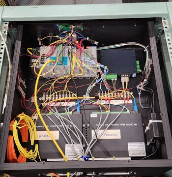
Fiber Optic Isolation
The ion source has two high-voltage regions that must be electrically isolated to prevent a short circuit. The regions are each referred to as the high and mid-potential regions respective of their relative voltage potential. Each region has a fiber optic link to relay contact closures or analog signals between the Interlock System and the sensors and control devices.
- Interlock System Enclosure (Ground Potential):
- • 2x Bidirectional contact closure fiber transceivers
- • Analog voltage signal fiber receiver
- Mid-potential Area:
- • Bidirectional contact closure fiber transceiver
- • Analog voltage signal fiber transmitter
- High-potential Area:
- • Bidirectional contact closure fiber transceiver
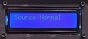
LCD Screen
The screen is a commonly used 1602 LCD module with a built in HD44780 controller. It can display 2 lines of up to 16 characters. It receives display commands from the P1AM- GPIO shield.
Sensors
- • Cage door contacts
- • Fume hood flow switch
- • Vacuum gauge threshold relays
- • Vacuum gauge analog output
- • Tritium detector threshold relay
- • Tritium detector analog output
- • Building power monitor relay
- • Coolant flow switches
- • Smoke detector
- • Titanium sublimation pump analog output
Firmware
The P1AM-100 controller uses Arduino IDE or ProductivityBlocks for programming. For this project, the firmware was written in C++.
The source code is here https://fsunuc.physics.fsu.edu/git/jgibbons3/Multi-SNICS_Interlock.git
Trouble Modes
Each of the sensors monitored by the interlock system are mapped to an appropriate response state to shutdown or lock out the Multi-SNICS injector and its power supplies in the event of an irregularity or trouble.
| Cage Door Trip | Vacuum Trip | Source Trip | |
|---|---|---|---|
| Input Conditions | Cage Door Contact | Vacuum Condition (Gnd) Vacuum Condition (Mid) |
Emergency Source Trip Switch Fume Hood Flow Switch Tritium Monitor Relay Building Power Failure Relay Smoke Detector |
| Output Relays | Pre-accelerator Supply Off Other High-Power Supplies Off |
Pre-accelerator Supply Off Other High-Power Supplies Off Both Gate Valves Closed Ionizer Off |
Pre-accelerator Supply Off Other High-Power Supplies Off Both Gate Valves Closed Ionizer Off Boiler Off |
Data Server
Contact
| Primary Contact: | Ingo Wiedenhoever mailto:iwiedenhoever@fsu.edu Ashton Morelock mailto:amorelock@fsu.edu | |
| Interlock: | Jonah Gibbons mailto:jgibbons3@fsu.edu Ryan Tang mailto:rtang@fsu.edu |


