ANASEN: Difference between revisions
| Line 49: | Line 49: | ||
Suppose we know the position on the SuperX3, thus, we have 3 pieces of information <math> \vec{p_0} = (x_0, y_0, z_0)</math>. And We have 2 wires ID. Each wire and the <math>\vec{p_0} </math> will form a plan, the intersection line of the 2 plans will give us the first approximation of the beam trace. | Suppose we know the position on the SuperX3, thus, we have 3 pieces of information <math> \vec{p_0} = (x_0, y_0, z_0)</math>. And We have 2 wires ID. Each wire and the <math>\vec{p_0} </math> will form a plan, the intersection line of the 2 plans will give us the first approximation of the beam trace. | ||
Each wire is constructed from 2 points, let them be <math> \vec{a_i} </math> and <math> \vec{b_i} </math>, where < | Each wire is constructed from 2 points, let them be <math> \vec{a_i} </math> and <math> \vec{b_i} </math>, where <math> i </math> is the wire ID. The plan formed by the points <math> \vec{p_0}, \vec{a_i}, \vec{b_i} </math> has normal <math> \vec{n_i} = (\vec{p_0} - \vec{a_i}) \times (\vec{p_0} - \vec{b_i}) </math>. The vector for the line intersects between the 2 plans constructed by wire ID <math> i, j</math> and point </math> \vec{p_0}</math> is <math> \vec{N_{ij}} = \vec{n_i} \times \vec{n_j} </math>. Thus, the beam trace has an equation of <math> \vec{r} = \vec{p_0} + s \vec{N_{ij}} </math>, where <math> s </math> is the coordinate on the line. | ||
Revision as of 01:43, 14 January 2024
Array for Nuclear Astrophysics and Structure with Exotic Nuclei (ANASEN) is an active target detector. FSU, LSU, and TAM are joined in the development of the project.
First Generation
NIM paper : https://doi.org/10.1016/j.nima.2017.07.030 PRC paper : https://doi.org/10.1103/PhysRevC.105.055806
Second Generation
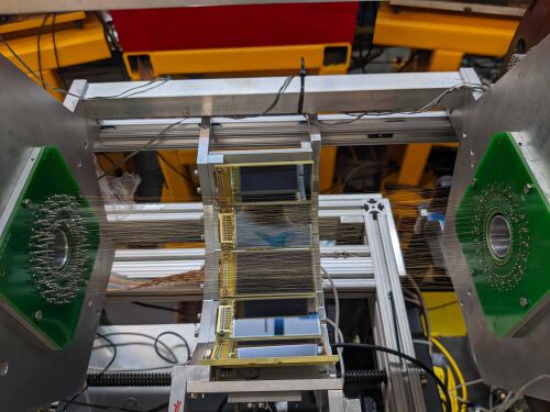
The main difference from the 1st generation is the Twisted Anode and Cathode wires.
Basics Geometry
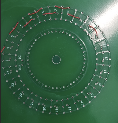
There are 5 Layers on the radial position of the ANASEN.
| Structure | Radius [mm] |
|---|---|
| ionizing wires | 23 |
| Graurd wires | 33 |
| Anode wires | 38 |
| Cathode wires | 43 |
| SuperX3 Silicon | 88 |
Twisted Anode and Cathodes
Readout
SuperX3 Silicon Detector Array
There are 24 Super-X3 double-sided Silicon detectors on the wall of the ANASEN. They are placed 88 mm away from the beam axis. Each of them has 75 mm X 40 mm sensitive area. Thus, the super-X3 covers a forward and backward angle of 40 deg.
Readout
Tracking for the twisted wire configuration
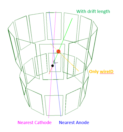
A beam trace consists of 5 parameters: 3 from a point and 2 from the trace angle . Thus, to reconstruct the beam trace, we need at least 5 pieces of information.
Suppose we know the position on the SuperX3, thus, we have 3 pieces of information . And We have 2 wires ID. Each wire and the will form a plan, the intersection line of the 2 plans will give us the first approximation of the beam trace.
Each wire is constructed from 2 points, let them be and , where is the wire ID. The plan formed by the points has normal . The vector for the line intersects between the 2 plans constructed by wire ID and point </math> \vec{p_0}</math> is . Thus, the beam trace has an equation of , where is the coordinate on the line.


