LINAC
NEED PROOF READING
Power Outage Procedure
When the building power is interrupted the Helium liquefier will stop along with its associated compressors. After this happens the linac boil off will begin to vent through a 1” pressure relief valve located behind the liquefiers. Do not be alarmed by this as it is designed to operate in this manner.
The linac chart recorder auto dialer will activate and someone on the linac list will be “beeped”. He will usually call the lab on the 644-6763 line before coming in. If no one calls within 15 minutes, call someone of the call list (see notice by phone in the control room).
Of the following procedure, item 1 should be done immediately after the emergency power comes on. Items 2 and 3 within 30 minutes or so, items 5 and 6 only if necessary.
- Open vacuum valves between the cryostats by switching the valve controllers FV5 thru FV8 to the manual open position. This allows the entire linac to be pumped by the turbomolecular and rotary pumps which are on emergency power.
- Make sure the turbo pumps on the buncher, cryostats B, C and D and the rebuncher have restarted. If not follow procedure posted by each pumping stations electronics rack.
- Close the J. T. valve on the liquefier (this is the micrometer handled valve) a fraction of a turn clockwise until you feel resistance.
- Now wait and monitor:
- Pressures: 1K dewar, linac and compressor return.
- Vacuums in all cryostats.
- LN2 and LHe levels in the 1K dewar and cryostats.
- Resonator and solenoid temperatures.
- As each cryostat runs out of LHe and its resonators (and solenoids) start to warm up:
- Pump the helium out of the slow tuners.
- Run down the persistent currents in the solenoids.
Helium Refrigerator Restart Procedure
- Turn on the load 2 RS compressors (look in the log book for information on which 2 were being used) using compressor start buttons on the liquefier.
- Defrost o-rings on relief valves as required.
- Start the appropriate liquefier:
- Push the liquefier start button.
- Turn the flywheel c.c.w. until the machine starts to run.
- Open the J. T. valve to 0.085.
- Return FV5 thru FV8 to auto position.
- Restart the turbopumps just upstream from the 90◦ magnet and on the switching magnet (note: before starting the tumbopumps, make sure the foreline pumps are running and the ball valves to the turbos have been re-opened with foreline vacuum < 50 m.)
Super Fast Valve Reset Procedure
The super fast valve operates with the spark-gap vacuum protection system on the beamlines to the various experimental stations. If vacuum is lost downstream of the switching magnet this valve will quickly close to prevent vacuum loss in the Linac cryostats. Once this valve has fired it must be “rearmed” using the following procedure:
- Switch the S.F.V. controller (located in the vacuum protection rack) to disarmed.
- Disconnect the cable from the back panel of the controller labeled to valve.
- Using a 7/64 allen wrench loosen the two hex head bolts that attach the trigger mechanism to the top of the valve body.
- Using a pair of vise-grips remove the spent squib from the trigger device and replace it with a new one from the can located on switching magnet.
- Make sure there is good contact between the pin on the squib and the connector on the cable from the controller.
- Hook up the air line (nylon tubing with nu-pro valve next to the valve) to the swagelok fitting on the side of the valve body and open the nupro valve. The valve stem should emerge from the hole in the top of the valve body after this occurs, close the nupro valve and remove the air line.
- Hook up the cable on the controller marked “to valve” again and then switch the control unit to the “Test” position. Push the reset button and then switch the controller to the armed position.
Troubleshooting Linac out of Lock Problems
If the L.E. Bunching system and the Linac resonators are ‘in-lock’, the % in-lock meter in the control room should read 100%. If the reading is zero or unsteady, the following should be checked:
- Is the L.E. buncher phase lock O.K.? see 43.3.1.
- Are any of the resonators “out of lock”? See 43.3.2.
- If several resonators are simultaneously out of lock (their LED’s on the resonator display panel are flickering), one or more cryostats are probably filling with the LN2.
- Go to the LINAC Hall and check the status of the “fill” indicator lights on the LN2 controllers which are located on the instrumentation racks hanging from the blue radiation shield wall. If one or more of these indicator lights is illuminated, you will have to wait for all of them to stop filling before further diagnosis can be made.
Troubleshooting Loss of Beam Phase Lock
Look at the oscilloscope labeled “PHASE LOCK STATUS” in the LINAC electronics rack in the control room. If operating properly there should be a trace – the beam phase error signal – 1 division above ground, at the position marked ‘buncher’ on the scope. If this trace is a straight line at zero, or the top of the screen, or is very jumpy, the beam phase lock is not working properly. Check the following:
- Is there beam going through the phase detector, that is, is there beam on BS-2? See 2.
- Is the L.E. buncher “PHASE LOCK” phase set properly? See 3.
- Is the chopper phase set properly? See 4.
Bunching System: Buncher and Chopper
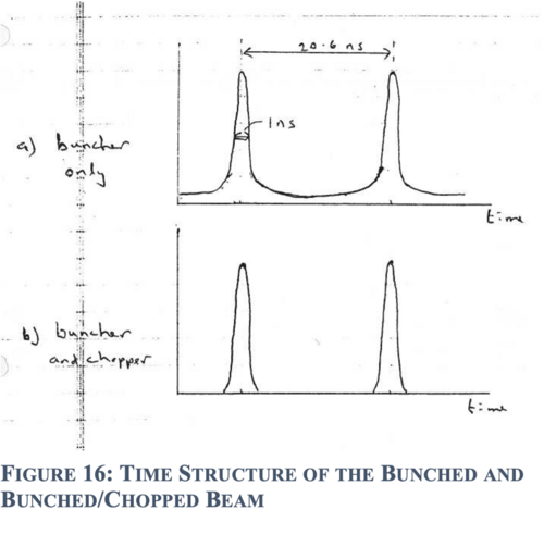
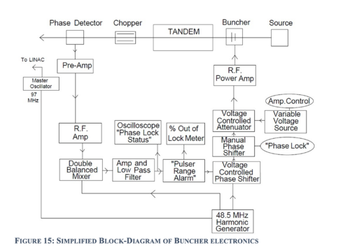
The d.c. beam from the ion source is bunched into a series of pulses, about 1 ns long and 20.6 ns apart by a gridded buncher at the L.E. end of the tandem, see figures 15 (a) and 1. The residual beam, about 50% of the total, between pulses, is swept away by a parallel plate chopper at the H.E. end of the tandem, see figures 15 (b) and 1. Because the beam pulses entering the LINAC must be precisely synchronized with the R.F. in the LINAC resonators, the L.E. buncher and chopper are both actively phase locked to the LINAC 97 MHz master oscillator.
The chopper R.F. Is phase locked to the M.O directly. However, this would be insufficient for the L.E. buncher because the transit time of the beam pulses from the L.E. buncher to the LINAC is sensitive to the ion source pre-acceleration voltage and to the condition of the tandem. Instead, the phase of the L.E. buncher is continuously varied to keep constant the time of arrival (or phase) of the beam pulses at the beam phase detector this is located just after the LINAC 90◦ magnet, see figure 1.
The buncher phase lock system, on its own, woks quite reliably. Unfortunately, the chopper, being located before the phase detector, makes the overall behavior more complicated. If for any reason, the beam pulses do become mis-phased by more than a ns or so, there are swept-away by the chopper and do not reach the phase detector. In this case, the phase detector still sees “pulses”, but of residual beam generated by the chopper instead. A spurious phase error signal is generated and the beam phase lock system may hang up.
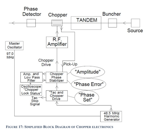
To overcome this the “pulser range alarm” unit, when it goes into out-of-lock mode, temporarily disables the feedback control of the L.E. buncher phase, and resets the L.E. buncher phase to that corresponding to zero phase error. In most cases this automatically unhangs the system and allows the feedback system to lock up again. The chopper phase lock system uses an R.F. pick-up signal from the chopper itself and is independent of the beam; see figure 17
- Check beam current on BS-2
- Temporarily disconnect the chopper drive cable – the cable from the output of the “chopper stabilizer” unit to the patch panel “To 24 MHz CHOPPER” at the patch panel. Insert BS-2 and check the current. If the beam has fallen off considerably – (you should know what it is supposed to be!) – you must get the current back before proceeding. Investigate:
- Source output: Insert the L.E. cup.
- Transmission through the tandem, has the foil gone bad? Insert C-1.
- If the beam on BS-2 is O.K. with the chopper off, but is greatly reduced when the chopper is reconnected, check the phasing of the buncher and chopper, see 3 and 4.
- Adjusting the L.E. buncher “PHASE LOCK”
- Temporarily disconnect the chopper drive cable to disable the chopper (see 2). The beam phase error signal on the “PHASE LOCK STATUS” scope should be 1 division above ground. If it is not, adjust the “PHASE LOCK” knob on the electronics rack to bring the trace to the correct position. When properly set the trace should move upwards as the knob is rotated clockwise.
If you are unable to get a reasonably steady trace (it should have slight line frequency wiggle on it) then: There is something else wrong with the L.E. buncher system. See 5 or get help.or, more likely, the tandem and/or ion source are unstable. If the correct phase error signal is seen, next recheck the chopper phasing, see next section, 4.
Setting Chopper PHASE
With the beam on BS-2 and the L.E. buncher properly set (i.e. the beam phase error signal is 1 division above zero), reconnect the chopper drive cable. Ideally the beam on BS-2 should fall by about 50%. If reconnecting the chopper causes the current on BS-2 to fall by more than 50%, adjust the PHASE SET knob on the “TAC AND CHOPPER DRIVE” until the beam on BS-2 is maximized and is nearly 50% of the unchopped beam, and also, the beam phase error signal is properly located 1 division above zero. Note that readjustment of the beam “PHASE LOCK” knob is sometimes required.
If you are unable to achieve a stable beam phase lock with the chopper on, it usually means that the ion source and tandem are too unstable for the phase lock system to keep the beam pulses going through the time window set by the chopper. If time and energy resolution are of no concern, the system can be made more stable by reducing the chopper amplitude, see 7. You should also check the chopper phase lock, see 6.
Check the L.E. Buncher Field Level
Use the LINAC oscilloscope, channel 1, 50Ω , to look at the “48.5 MHz buncher pick-up” on the patch panel in the control room. Leave the 20dB attenuator in place. The peak-to-peak voltage should agree with the value recorded in the log book during run set up, as the optimum L.E. buncher setting.
If the pick-up signal is much lower (a few percent is not significant) there is a problem with the L.E. buncher system.
Check Chopper Phase Lock
(The chopper is phase locked directly to the master oscillator. The system is independent of the beam, and so in general does not need adjustment.) When the chopper is connected, the “chopper phase lock” trace, the lower trace on the “PHASE LOCK STATUS” scope, should be at 2.5 divisions below zero. If it is way off, the chopper R.F. amplifier is off, or a cable has probably not been connected properly. If the trace is slightly displaced from its set point, adjust the “PHASE ERROR” knob on the “chopper stabilizer” to bring the trace back to 2.5 divisions below zero.
Adjustment of Chopper Amplitude
The amplitude of the R.F. electric field in the chopper can be adjusted using the knob on the “chopper stabilizer” unit labeled amplitude. Reducing the amplitude makes the chopping looser. This usually makes the buncher “phase lock” system more stable, but worsens the energy and time resolution of the LIONAC beam.
Make sure you note the old and new chopper amplitude settings.
Resonator Lock Status
If one of the Linac resonators goes ‘out of lock’, its associated light on the resonator status display will illuminate. The control electronics for a resonator will generate and
O/L indication if the error signals in the feedback loops used to control the resonator field level or phase are excessive. After identifying the problem resonator go to the Linac hall and check the following:
- Is the cryostat filling with LN2?
- Is the pin diode pulser (P.D.P.) tripped? See 1 below.
- Is the resonator phase lock and field level correct? See 2 below.
- Does the R.F. amplifier have power?
To check the status of the amplifier do not depend on the indicator light, instead look for meter indication or feel behind the unit for operation of the fan.
Checking the Pin Diode Pulser (P.D.P.) for proper operation.
P.D.P. tripped on overcurrent: First check the P.D.P. overcurrent indicator (figure 18) for the out-of-lock resonator. If illuminated push and release the red reset button on the front of the unit. This will reset the interlock and should restore the P.D.P. to normal operation. If the P.D.P. will not reset after a few attempts or continues to trip frequently call someone on the Linac call list for assistance.
Checking the P.D.P. for correct operational: If the P.D.P. is not tripped the current and voltage output can be checked. First turn off the R.F. amplifier then switch the P.D.P to the ‘off’ position. 500V should be indicated and 0 current. Next switch to the ‘Auto’ position. There should be approximately 1A current and 0V indicated. If either of the above readings are not observed call someone on the Linac call list for help. Finally, note the present setting of the VCX gain knob on the S.T.C. then set it to minimum. You should see a clean square wave with a slight sloping top. If not, get help. Reset the VCX gain knob.
Checking for proper phase lock and field level
Use the Tektronics 2445A dedicated Linac scope and select the recall 3 program option. The scope should be set up as follows figure 18 A and B. The time base should be set to 20 µsec. CH.1 is connected to the can mon. (100mV/div./50Ω) CH.2 is connected to the P.D.P. mon. (500mV/div./1M) CH.3 is connected to the phase error (0.1V/div.) CH.4 is connected to the P.W. clockout (0.1V/div.) trigger the scope on CH.4. For a normally operating resonator the trace illustrated in figure 19 should be observed. After setting up the scope check the following:
First check that the resonator is operating at the proper field level. The peak-to-peak amplitude of the can mon. signal on the scope should match (±20mV) the LEV SET value for that resonator on the Linac control screen. Look at the monitor near the cryostat C. If the can mon. is less than the LEV SET the resonator is ‘normal’, multipactoring or the self excited loop phase control is misadjusted, see a and b.
If the field level is O.K. focus on the P.D.P. monitor and phase error signals:
If the P.D.P. monitor signal shows no resemblance to a square wave (figure 19) (even a ‘smeared’ out one), i.e. the trace is a line at 0V or near 1V, the P.D.P. is not switching.


