FRIB SOLARIS Collaboration
The collaboration focuses on the development of the DAQ for the SOLARIS spectrometer.
Kinematic with DWBA Simulation
A web page is created for a simulation. Here
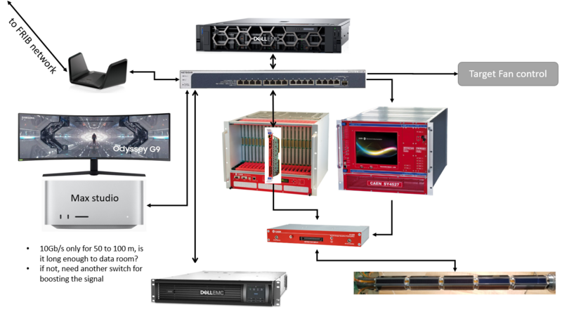
proposed schematics
The DAQ system will be contained within a private network provided by the Netgear nighthawk wifi router and a 16 ports 10Gb/s switch with a total data capacity of 320 Gb/s. The 16 ports switch is chosen for adding more digitizers in the future. The DAQ computer will be a rack server Dell R7525 with 2 CPU (total 32 core with 64 thread), 64 GB RAM, and a lot of storage. The primary mission of the DAQ computer is to control and readout the digitizer. It is also served as the database and achieves data server (also for background parallel data analysis). The DAQ will be protected by a UPS unit with 2700W and 8 outlets, sufficient to provide power for the DAQ computer, the Crate, the HV supply, and other devices. The DAQ computer (2U), the router (1U), the HV supply (8U), the Crate (8U), and UPS (2U) will be in one rack of 25U (StarTech.com 25U Open Frame Server Rack). Finally, there will be a Mac for remote control and analysis. I suggest a Mac studio (Apple M1 Max chip 10-core) and a 49-inch-wide screen monitor (Samsung 49-inch Odyssey G9).
| Item | Config | size | Price |
|---|---|---|---|
| Rack server | Dell PowerEdge R755 | 2U | ~ $8000 |
| AMD EPYC 3.0 GHz 16C/32T x 2 | |||
| 16 GB x 4 3200 GHz RAM | |||
| 12 (front) + 2 (rear) 3.5" HDD slots | |||
| 10Gb/s ethernet dual ports | |||
| Mass storage | 16 TB HDD x 6 (Raid 6) = 64 TB + 32 TB fail-safe | ~ $2400 | |
| HD tray | WORKDONE 12-Pack - 3.5" Hard Drive Caddy | ~ $200 | |
| Temp storage | 8 TB SSD SATA | ~ $700 | |
| 19' rack | StarTech.com 25U Open Frame Server Rack | ~$300 | |
| UPS | DELL EMC SmartUPS 3000 SMARTCONNECT 120V RM, 6 + 2 output | 2U | ~ $1900 |
| Network | Netgear nighthawk wifi router + 16 x 10Gb/s, 320 Gb/s switch | 1U | ~$2400 |
| Mac + monitor | Max studio (M1 10-core) + Samsung Odyssey G9 49-inch | ~$3000 |
Hardware
| Item | Config | size |
|---|---|---|
| Rack server | Dell PowerEdge R7525 | 2U |
| AMD EPYC 7302 3.0 GHz 16C/32T x 2 = 64 cores | ||
| 16 GB x 8 3200 GHz RAM = 128 GB | ||
| 12 (front) + 2 (rear) 3.5" HDD slots | ||
| 10Gb/s ethernet dual ports | ||
| Mass storage | 2 X (16 TB HDD x 6 (Raid 10) = 48 TB + 48 TB fail-safe) | |
| Temp storage | 8 TB SSD SATA | |
| UPS | TRIPPLITE SU30000RTXLCD3U, 3000VA 2700W | 3U |
| Network | 24-port PPoE 1Gb switch + 8-port 10Gb switch | |
| Mac | Max studio (2023 version, M1 Ultra 20-core, 48-core GPU, 32-core Neural Engine, 64GB RAM, 4TB SSD) |
Rack Server
The rack server is a Dell PowerEdge R7525. It has total of 64 cores with 3.0 GHz.
storage
The OS disk is at one of the rear HD slot. It has 1.98 TB capacity and Ubuntu 22.04 was installed.
There is another slot at the rear. but it is using small from factor. We have a 8 TB SSD waiting.
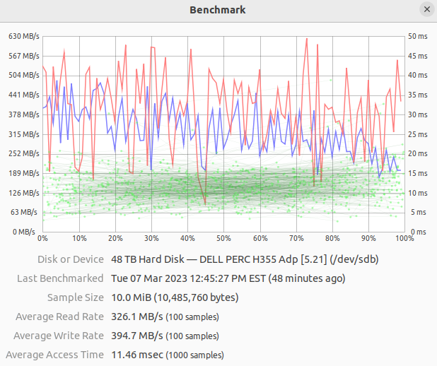
12 x 16TB hard disks were installed in the front panel. They are divided into 2 groups, 6 for raw data storage, 6 for trace analysis. Both groups are RAID10 array. They have read/write speed of 326/394 MB/s. In theory, it can support 3 10Gb/s in full speed.
OS, software, and services
An Ubuntu 22.04 is used for the OS.
Internal:SOLARIS Rack DAQ Setup
local network
The server has 2-port of 10Gb/s Ethernet. One is connected to a 8-port 10Gb/s switch for digitizers. another one is connect to the Mac studio.
Although each digitizer has 10Gb/s Ethernet port, the actual data rate would be far lesser. In present setting, 7 digitizers are connected to the 10Gb/s switch that the maximum data rate is 1.25GB/s.
There are 2 short PCI slots and 2 normal PCI slots for future extensions, such as 25Gb/s optical fiber ports, or additional 10Gb/s Ethernet ports.
FSU SOLARIS DAQ
The SOLARIS DAQ uses the 2nd generation CAEN digitizer VX2745. The communication library is totally different from the 1st generation digitizer, which makes the SOLARIS DAQ different from the FSU DAQ.
The FSU SOLARIS DAQ contains the following ingredients:
- Complete control of the CAEN 2nd digitizers VX2745 with PDD-PHA firmware.
- Scope for single channels, to display 2 analog traces and 4 digital traces.
- Data merging and sorting
- Connection to Database (optional)
- Connection to ELog (optional)
The DAQ program can be used as a general DAQ, not SOLARIS-oriented. However, it will come with
- SOLARIS-oriented control panel
- HV controller
- Target fan controller
And also (in a separate git repository)
- Online analysis code
Architecture
The main ingredient of the DAQ is the ClassDigitizer2Gen.h . It is a standalone C++ class for controlling and readout of a 2nd gen digitizer. It has methods specialized for DPP-PHA firmware. By using this class, a command-line DAQ can be developed. By having the digitizer controller separated from the GUI, it is easier to maintain.
The SOLARIS DAQ is using Qt6 for GUI development, after comparing CERN ROOT GUI, Gtk4, and IMGUI. IMGUI is fast and nice due to the GPU rendering, but it cannot be ssh and is limited by GPU. CERN ROOT GUI is actually using Qt4 with a ROOT modification. It provides a very good histogram, and scatter plots support, but it is not as rich as Qt6 for UI elements. Gtk4, the syntax is C-style, not C++, which is very alien to me. Although I use Qt6 for development, I did not use the Qt creator and the ui files for UI, it a simply code-based UI development.
The mainWindow.h is the, well, main window for the GUI.
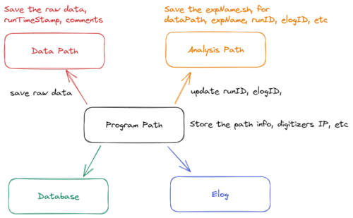
The folder structure of the DAQ is shown in the figure on the right-handed side.
- the program's local folder -- this stores the programSettings.txt
- the raw data path -- this stores the raw data
- the analysis path -- this stores the expName.sh, which is updated by the DAQ for the runID, elogID, raw data path, and expName etc.
Data Reading and Structure
The new CAEN FeLib has two modes for data reading.
- Raw endpoint -- can get a chuck of data at 1 read-out. But the data needs to be decoded, and decoding requires time.
- DPP-PHA endpoint -- can only get 1 channel at a time, but the data is already decoded.
I tested the speed of the 2 methods. It turns out the DPP-PHA method is faster.
The syntax for getting these two endpoints are shown in the following.
Raw endpoint
uint64_t ep_handle;
CAEN_FELib_GetHandle(dev_handle, "/endpoint/raw", &ep_handle);

uint64_t ep_folder_handle;
CAEN_FELib_GetParentHandle(ep_handle, NULL, &ep_folder_handle);
CAEN_FELib_SetValue(ep_folder_handle, "/par/activeendpoint", "raw");

CAEN_FELib_SetReadDataFormat(ep_handle,
      " [ \
           { \"name\": \"DATA\",     \"type\": \"U8\", \"dim\": 1 }, \
           { \"name\": \"SIZE\",     \"type\": \"SIZE_T\" }, \
           { \"name\": \"N_EVENTS\", \"type\": \"U32\" }, \
        ]"
    );

uint8_t* data = new uint8_t[200000];
size_t  size;  /// number of byte of the data
uint32_t n_events;

CAEN_FELib_ReadData(ep_handle, 100, data, &size, &n_events );
DPP-PHA endpoint
uint64_t ep_handle;
ret = CAEN_FELib_GetHandle(dev_handle, "/endpoint/dpppha", &ep_handle);
//---------- configure endpoint
uint64_t ep_folder_handle;
ret = CAEN_FELib_GetParentHandle(ep_handle, NULL, &ep_folder_handle);
ret = CAEN_FELib_SetValue(ep_folder_handle, "/par/activeendpoint", "dpppha");
ret = CAEN_FELib_SetReadDataFormat(ep_handle,
" [ \
{ \"name\" : \"CHANNEL\", \"type\" : \"U8\" }, \
{ \"name\" : \"TIMESTAMP\", \"type\" : \"U64\" }, \
{ \"name\" : \"FINE_TIMESTAMP\", \"type\" : \"U16\" }, \
{ \"name\" : \"ENERGY\", \"type\" : \"U16\" }, \
{ \"name\" : \"ANALOG_PROBE_1\", \"type\" : \"I32\", \"dim\" : 1 }, \
{ \"name\" : \"ANALOG_PROBE_2\", \"type\" : \"I32\", \"dim\" : 1 }, \
{ \"name\" : \"DIGITAL_PROBE_1\", \"type\" : \"U8\", \"dim\" : 1 }, \
{ \"name\" : \"DIGITAL_PROBE_2\", \"type\" : \"U8\", \"dim\" : 1 }, \
{ \"name\" : \"DIGITAL_PROBE_3\", \"type\" : \"U8\", \"dim\" : 1 }, \
{ \"name\" : \"DIGITAL_PROBE_4\", \"type\" : \"U8\", \"dim\" : 1 }, \
{ \"name\" : \"ANALOG_PROBE_1_TYPE\", \"type\" : \"U8\" }, \
{ \"name\" : \"ANALOG_PROBE_2_TYPE\", \"type\" : \"U8\" }, \
{ \"name\" : \"DIGITAL_PROBE_1_TYPE\", \"type\" : \"U8\" }, \
{ \"name\" : \"DIGITAL_PROBE_2_TYPE\", \"type\" : \"U8\" }, \
{ \"name\" : \"DIGITAL_PROBE_3_TYPE\", \"type\" : \"U8\" }, \
{ \"name\" : \"DIGITAL_PROBE_4_TYPE\", \"type\" : \"U8\" }, \
{ \"name\" : \"WAVEFORM_SIZE\", \"type\" : \"SIZE_T\" }, \
{ \"name\" : \"FLAGS_LOW_PRIORITY\", \"type\" : \"U16\"}, \
{ \"name\" : \"FLAGS_HIGH_PRIORITY\", \"type\" : \"U16\" }, \
{ \"name\" : \"EVENT_SIZE\", \"type\" : \"SIZE_T\" } \
] \
"
);
uint8_t channel;
uint64_t timestamp;
uint16_t fine_timestamp;
uint16_t energy;
int32_t* analog_probes[2];
uint8_t* digital_probes[4];
analog_probes[0] = new int32_t[512];
analog_probes[1] = new int32_t[512];
digital_probes[0] = new uint8_t[512];
digital_probes[1] = new uint8_t[512];
digital_probes[2] = new uint8_t[512];
digital_probes[3] = new uint8_t[512];
uint8_t analog_probes_type[2];
uint8_t digital_probes_type[4];
size_t n_samples;
uint16_t flags_low_priority;
uint16_t flags_high_priority;
size_t event_size;
ret = CAEN_FELib_SendCommand(dev_handle, "/cmd/armacquisition");
ret = CAEN_FELib_SendCommand(dev_handle, "/cmd/swstartacquisition");
ret = CAEN_FELib_ReadData(ep_handle, 100,
&channel,
×tamp,
&fine_timestamp,
&energy,
analog_probes[0],
analog_probes[1],
digital_probes[0],
digital_probes[1],
digital_probes[2],
digital_probes[3],
&analog_probes_type[0],
&analog_probes_type[1],
&digital_probes_type[0],
&digital_probes_type[1],
&digital_probes_type[2],
&digital_probes_type[3],
&n_samples,
&flags_low_priority,
&flags_high_priority,
&event_size
);
Setting for Coincidence Trigger
This involve the following settings
| setting | type | domain | example |
|---|---|---|---|
| ChannelsTriggerMask | byte | ch | ch-i is the i-bit or (1 << i), so, for ch-1 and ch-2, put 6. |
| GlobalTriggerSource | string | dig | |
| EventTriggerSource | string | dig | |
| CoincidenceMask | ch | ||
| AntiCoincidenceMask | ch | ||
example 1
Suppose there are 2 input signals to ch-1 and ch-2. And We want ch-2 to be recorded when ch-1 is triggered.
example 2
Suppose there are 2 input signals to ch-1 and ch-2, And we want ch-2 to be recorded when ch-1 and ch-2 are both triggered.


