FSU SOLARIS DAQ
The SOLARIS DAQ uses the 2nd generation CAEN digitizer VX2745. The communication library is totally different from the 1st generation digitizer, which makes the SOLARIS DAQ different from the FSU DAQ.
The code can be downloaded from:
- https://fsunuc.physics.fsu.edu/git/rtang/SOLARIS_QT6_DAQ (developement)
- https://github.com/goluckyryan/SOLARIS_DAQ (stable)
The FSU SOLARIS DAQ contains the following ingredients:
- Complete control of the CAEN 2nd digitizers VX2745 with PDD-PHA firmware.
- Scope for single channels, to display 2 analog traces and 4 digital traces.
- Data merging and sorting
- Connection to Database (optional)
- Connection to ELog (optional)
The DAQ program can be used as a general DAQ, not SOLARIS-oriented. However, it will come with
- SOLARIS-oriented control panel
- HV controller
- Target fan controller
And also (in a separate git repository)
Architecture
The main ingredient of the DAQ is the ClassDigitizer2Gen.h . It is a standalone C++ class for controlling and readout of a 2nd gen digitizer. It has methods specialized for DPP-PHA firmware. By using this class, a command-line DAQ can be developed. By having the digitizer controller separated from the GUI, it is easier to maintain.
The SOLARIS DAQ is using Qt6 for GUI development, after comparing CERN ROOT GUI, Gtk4, and IMGUI. IMGUI is fast and nice due to the GPU rendering, but it cannot be ssh and is limited by GPU. CERN ROOT GUI is actually using Qt4 with a ROOT modification. It provides a very good histogram, and scatter plots support, but it is not as rich as Qt6 for UI elements. Gtk4, the syntax is C-style, not C++, which is very alien to me. Although I use Qt6 for development, I did not use the Qt creator and the ui files for UI, it a simply code-based UI development.
The mainWindow.h is the, well, main window for the GUI.
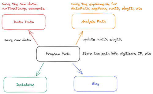
The folder structure of the DAQ is shown in the figure on the right-handed side.
- the program's local folder -- this stores the programSettings.txt
- the raw data path -- this stores the raw data
- the analysis path -- this stores the expName.sh, which is updated by the DAQ for the runID, elogID, raw data path, and expName etc.
Analysis Path
The analysis folder should contain the following sub-folders
- working
- working/Settings
- working/Logs
Although the setting file will be saved with the raw data for each run, the working/Settings stores the custom settings files.
The Logs folder stores the Log msg. There are other logs msg from stdout, saved under a Logs folder inside the program's local folder.
Initial Settings of the DAQ after installation
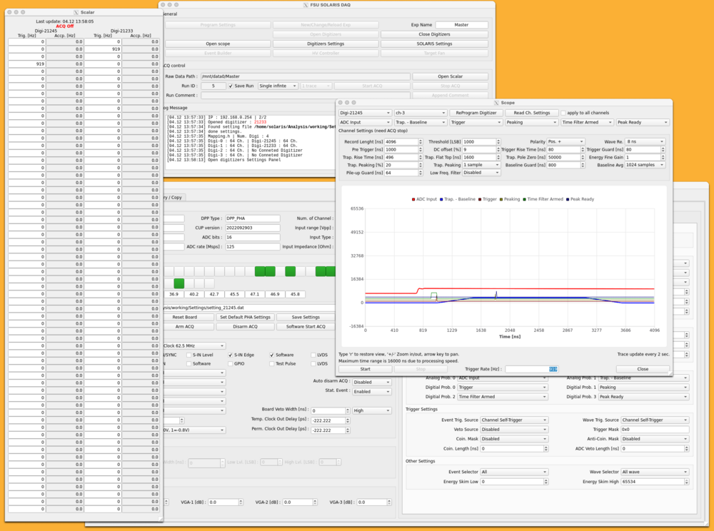
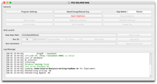
Once the DAQ is installed and open, a main window is opened (see the left picture).
Two folders are required:
- Data Path and Root Data Path, these two paths can be the same.
- Analysis Path : this is the analysis code. The expName.sh will be stored inside. expName.sh saved the run number, expName, etc.
Before open digitizer, Click the Program Settings to define the paths, database IP and Name, and Elog IP. These settings will be saved in the Settings Save Path.
Data Reading and Structure
The new CAEN FeLib has two modes for data reading.
- Raw endpoint -- can get a chuck of data at 1 read-out. But the data needs to be decoded, and decoding requires time.
- DPP-PHA endpoint -- can only get 1 channel at a time, but the data is already decoded.
I tested the speed of the 2 methods. It turns out the DPP-PHA endpoint method is faster.
The syntax for getting these two endpoints are shown in the following.
Raw endpoint
uint64_t ep_handle;
CAEN_FELib_GetHandle(dev_handle, "/endpoint/raw", &ep_handle);

uint64_t ep_folder_handle;
CAEN_FELib_GetParentHandle(ep_handle, NULL, &ep_folder_handle);
CAEN_FELib_SetValue(ep_folder_handle, "/par/activeendpoint", "raw");

CAEN_FELib_SetReadDataFormat(ep_handle,
      " [ \
           { \"name\": \"DATA\",     \"type\": \"U8\", \"dim\": 1 }, \
           { \"name\": \"SIZE\",     \"type\": \"SIZE_T\" }, \
           { \"name\": \"N_EVENTS\", \"type\": \"U32\" }, \
        ]"
    );

uint8_t* data = new uint8_t[200000];
size_t  size;  /// number of byte of the data
uint32_t n_events;

CAEN_FELib_ReadData(ep_handle, 100, data, &size, &n_events );
DPP-PHA endpoint
uint64_t ep_handle;
ret = CAEN_FELib_GetHandle(dev_handle, "/endpoint/dpppha", &ep_handle);
//---------- configure endpoint
uint64_t ep_folder_handle;
ret = CAEN_FELib_GetParentHandle(ep_handle, NULL, &ep_folder_handle);
ret = CAEN_FELib_SetValue(ep_folder_handle, "/par/activeendpoint", "dpppha");
ret = CAEN_FELib_SetReadDataFormat(ep_handle,
" [ \
{ \"name\" : \"CHANNEL\", \"type\" : \"U8\" }, \
{ \"name\" : \"TIMESTAMP\", \"type\" : \"U64\" }, \
{ \"name\" : \"FINE_TIMESTAMP\", \"type\" : \"U16\" }, \
{ \"name\" : \"ENERGY\", \"type\" : \"U16\" }, \
{ \"name\" : \"ANALOG_PROBE_1\", \"type\" : \"I32\", \"dim\" : 1 }, \
{ \"name\" : \"ANALOG_PROBE_2\", \"type\" : \"I32\", \"dim\" : 1 }, \
{ \"name\" : \"DIGITAL_PROBE_1\", \"type\" : \"U8\", \"dim\" : 1 }, \
{ \"name\" : \"DIGITAL_PROBE_2\", \"type\" : \"U8\", \"dim\" : 1 }, \
{ \"name\" : \"DIGITAL_PROBE_3\", \"type\" : \"U8\", \"dim\" : 1 }, \
{ \"name\" : \"DIGITAL_PROBE_4\", \"type\" : \"U8\", \"dim\" : 1 }, \
{ \"name\" : \"ANALOG_PROBE_1_TYPE\", \"type\" : \"U8\" }, \
{ \"name\" : \"ANALOG_PROBE_2_TYPE\", \"type\" : \"U8\" }, \
{ \"name\" : \"DIGITAL_PROBE_1_TYPE\", \"type\" : \"U8\" }, \
{ \"name\" : \"DIGITAL_PROBE_2_TYPE\", \"type\" : \"U8\" }, \
{ \"name\" : \"DIGITAL_PROBE_3_TYPE\", \"type\" : \"U8\" }, \
{ \"name\" : \"DIGITAL_PROBE_4_TYPE\", \"type\" : \"U8\" }, \
{ \"name\" : \"WAVEFORM_SIZE\", \"type\" : \"SIZE_T\" }, \
{ \"name\" : \"FLAGS_LOW_PRIORITY\", \"type\" : \"U16\"}, \
{ \"name\" : \"FLAGS_HIGH_PRIORITY\", \"type\" : \"U16\" }, \
{ \"name\" : \"EVENT_SIZE\", \"type\" : \"SIZE_T\" } \
] \
"
);
uint8_t channel;
uint64_t timestamp;
uint16_t fine_timestamp;
uint16_t energy;
int32_t* analog_probes[2];
uint8_t* digital_probes[4];
analog_probes[0] = new int32_t[512];
analog_probes[1] = new int32_t[512];
digital_probes[0] = new uint8_t[512];
digital_probes[1] = new uint8_t[512];
digital_probes[2] = new uint8_t[512];
digital_probes[3] = new uint8_t[512];
uint8_t analog_probes_type[2];
uint8_t digital_probes_type[4];
size_t n_samples;
uint16_t flags_low_priority;
uint16_t flags_high_priority;
size_t event_size;
ret = CAEN_FELib_SendCommand(dev_handle, "/cmd/armacquisition");
ret = CAEN_FELib_SendCommand(dev_handle, "/cmd/swstartacquisition");
ret = CAEN_FELib_ReadData(ep_handle, 100,
&channel,
×tamp,
&fine_timestamp,
&energy,
analog_probes[0],
analog_probes[1],
digital_probes[0],
digital_probes[1],
digital_probes[2],
digital_probes[3],
&analog_probes_type[0],
&analog_probes_type[1],
&digital_probes_type[0],
&digital_probes_type[1],
&digital_probes_type[2],
&digital_probes_type[3],
&n_samples,
&flags_low_priority,
&flags_high_priority,
&event_size
);
DataFormat
The SOLARIS_DAQ provides 4 types of data formats.
For trace recording, the "wave save" must be "always", and "wave trig. source" cannot be disabled.
Everything, 47 + waveform_size * (12) byte
CHANNEL
TIMESTAMP
FINE_TIMESTAMP
ENERGY
ANALOG_PROBE_1
ANALOG_PROBE_2
DIGITAL_PROBE_1
DIGITAL_PROBE_2
DIGITAL_PROBE_3
DIGITAL_PROBE_4
ANALOG_PROBE_1_TYPE
ANALOG_PROBE_2_TYPE
DIGITAL_PROBE_1_TYPE
DIGITAL_PROBE_2_TYPE
DIGITAL_PROBE_3_TYPE
DIGITAL_PROBE_4_TYPE
WAVEFORM_SIZE
FLAGS_LOW_PRIORITY
FLAGS_HIGH_PRIORITY
TRIGGER_THR
TIME_RESOLUTION
BOARD_FAIL
FLUSH
AGGREGATE_COUNTER
EVENT_SIZE
One-Trace, 25 + waveform_size * 4 Byte
CHANNEL
TIMESTAMP
FINE_TIMESTAMP
ENERGY
ANALOG_PROBE_1
ANALOG_PROBE_1_TYPE
WAVEFORM_SIZE
FLAGS_LOW_PRIORITY
FLAGS_HIGH_PRIORITY
*TRIGGER_THR
*TIME_RESOLUTION
*BOARD_FAIL
*FLUSH
*AGGREGATE_COUNTER
*EVENT_SIZE

* read but not save
No Trace, 16 Byte
CHANNEL
ENERGY
TIMESTAMP
FINE_TIMESTAMP
FLAGS_LOW_PRIORITY
FLAGS_HIGH_PRIORITY
*TRIGGER_THR
*TIME_RESOLUTION
*BOARD_FAIL
*FLUSH
*AGGREGATE_COUNTER
*EVENT_SIZE

* read but not save
MinWithFineTimeStamp, 12 Bytes
CHANNEL
ENERGY
TIMESTAMP
FINE_TIMESTAMP
Minimum, 11 Bytes
CHANNEL
ENERGY
TIMESTAMP
For PSD firmware
For PSD, only ENERGY_SHORT of 2 bytes is added.
Data Rate
I test with 1-trace recording. Record length is 4096 ns, wave resolution is 8 ns. i.e. trace size is 512. Pulse signal sent to ch-0 with 64 kHz. The data rate is 112 MB/s, which is almost the limit of the ethernet cable. The test machine is Intel Xeon W-1250 CPU @ 3.3 GHz, RAM is DIMM DDR4 16GB 3200 MT/s single slot, HD is 16 TB mechanical drive.
For 1-trace, the data size is 25 bytes. the data size of the trace is 4 bytes times the trace size. For the above setting, the data size is 2073 bytes. For 64 kHz rate, 132672000 Byte/s = 126.5 MB/s.
The table below estimated the maximum trigger rate for 100 MB/s transmission of one board.
| Data Format | Trace Length [Sample] | Data Size [Byte] | Max rate for the whole board (average/ch) |
|---|---|---|---|
| Everything | 1024 (8 ns) | 12335 | 8.5 kHz ( 132 Hz / ch) |
| 512 (8 ns) | 6191 | 16.9 kHz ( 265 Hz / ch ) | |
| 1-Trace | 1024 (8 ns) | 4121 | 25.4 kHz ( 397 / ch ) |
| 512 (8 ns) | 2073 | 50.6 kHz ( 790 Hz / ch ) | |
| No Trace | N/A | 16 | 6.55 MHz ( 102.4 kHz / ch ) |
| Minimum | N/A | 11 | 9.5 MHz ( 148.9 kHz / ch ) |
| Mini + FineTime | N/A | 12 | 8.7 MHz ( 136 kHz / ch ) |
| Data Format | Trace Length [Sample] | Data Size [Byte] | Max rate for the whole board (average/ch) |
|---|---|---|---|
| No Trace | N/A | 18 | 5.83 MHz ( 91.0 kHz / ch ) |
| Minimum | N/A | 13 | 8.07 MHz ( 126 kHz / ch ) |
| Mini + FineTime | N/A | 14 | 7.5 MHz ( 117 kHz / ch ) |
Setting for Coincidence Trigger
This involves the following settings
| setting | type | domain | example |
|---|---|---|---|
| EventTriggerSource | string | ch | define the trigger source for energy and time |
| WaveTriggerSource | string | ch | define the trigger source for wave form |
| ChannelsTriggerMask | bit mask | ch | ch-i is the i-bit or (1 << i), so, for ch-1 and ch-2, put 6. |
| GlobalTriggerSource | string | dig | This is a global trigger to trigger all channels |
| CoincidenceMask | string | ch | Set the coincident mask |
| AntiCoincidenceMask | string | ch | Set the veto |
| ConicidentLengthT | number | ch | the coincident length in ns |
- Always record waveform samples and relative event parameters
Set ONLY the WaveTriggerSource
- Always record event parameters, and record the relative waveform samples only when there is space in the board memory buffer
Set BOTH WaveTriggerSource and EventTriggerSource
example 1 : Trigger by other channel
Suppose there are 2 input signals to ch-1 and ch-24. And We want ch-24 to be recorded when ch-1 is triggered.
/ch/0..63/par/EventTriggerSource   Ch64Trigger  // the trigger is controlled by ChannlesTriggerMask
/ch/0..63/par/WaveTriggerSource    Ch64Trigger  // for waveform recording
/ch/1/par/ChannelsTriggerMask      0x2          // it is equal to ch-1 self-trigger.
/ch/24/par/ChannelsTriggerMask     0x2          // ch-24 is triggered by ch-1
Notice that, ch-24 will be recorded no matter ch-24 has a signal or not.
example 2 : Trigger by coincident with other channel
Suppose there are 2 input signals to ch-1 and ch-23, And we want ch-23 to be recorded when ch-1 and ch-23 are both triggered.
/ch/1/par/EventTriggerSource     ChSelfTrigger
/ch/23/par/EventTriggerSource    ChSelfTrigger
/ch/23/par/CoincidenceMask       Ch64Trigger   // the CoincidentMask is the ChannelsTriggerMask
/ch/23/par/ChannelsTriggerMask   0x2
/ch/23/par/CoincidenceLengthT    40     // define the coincident window from ch-23
Meaning of CoincidenceLengthT
I tested the coincident window by sending ch-1 with a 1 kHz pulse, and ch-23 with 50 kHz Poisson pulses. After the event building using 100 ticks. The time difference with respect to ch-23 ranges from -10 ticks and 16 ticks for coincidenceLenght = 104 ns = 13 ticks. In addition, ch-23 arrives early then ch-1 by 6 thicks = 48 ns.
The coincident window is defined as +/- the triggering time of ch-23. For example. if ch-23 is triggered at t = 100 ns, ch-1 is triggered at t = 160 ns. The coincident time window of 40 ns has 80 ns width and middle at the mid-point if both trigger, i.e. t = 130 ns, starting from t = 90 ns to t = 170 ns.
example 3 : Anti coincident
Ch-18 is prohibited by the ch-0 trigger, but accept anything not coincident with ch-0.
/ch/0/par/EventTriggerSource     ChSelfTrigger
/ch/18/par/EventTriggerSource    ChSelfTrigger
/ch/18/par/CoincidenceMask       Disable
/ch/18/par/AntiCoincidenceMask   Ch64Trigger
/ch/18/par/ChannelsTriggerMask   0x1
/ch/18/par/CoincidenceLengthT    40
example 4 : Mutual coincident
Signals from ch-0 and ch-18 only be recorded when both channels are triggered.
We can use ITL to archive that.
ch-0/EventTriggerSource = Channel Self-Trigger
ch-0/Coincident Mask    = Channel 64 trigger
ch-0/Trigger Mask       = 0x40000000   # ch-30
ch-0/Coincident Length  = 104
ch-18/EventTriggerSource = Channel Self-Trigger
ch-18/Coincident Mask    = Channel 64 trigger
ch-18/Trigger Mask       = 0x1   # ch-1
ch-18/Coincident Length  = 104
I tested the setting, ch-0 and ch-18 have a coincident pulse with 10 Hz, pulse height of 23000 ch. And each of them has another uncorrelated 100 Hz pulse, pulse height of 7900 ch.
example 5 : Trigger other board
We have two boards this time, from board-0, ch-0, generate a TRG-OUT, the TRG-OUT is sent to TRG-IN in board-1, and triggers whatever channels.
in board-0, we can set the ch-0 to be part of the ITL-A. and TRG-OUT is ITL-A.
in board-1, set the coincident mask to be TRG-IN and the coincident length to be long enough.
Note that in the ITL-A Main Logic, if we pick AND, or Majority, the calculation is checked within one clock cycle, which is 62.5 MHz = 16 ns. If ch-0 and ch-18 are not both triggered within 16 ns, then no output of the ITL-A. That is why I picked the Main Logic to be OR.
example 6 : Mutual coincident between board-0 ch-0 and board-1 ch-1
In this case, we need a logic unit. board-0 ch-0 and board-1 ch-1 are included in ITLA, and the TRG-OUT are ITLA. The two TRG-OUT signals go to the logic unit and output a trigger pulse with an AND gate. The output goes back to TRG-IN for both board-0 and board-1. In board-1 ch-0 and board-0 ch-1 coincidentMask is TRG-IN and set the coincidentLenght.
(need to test)
Sync with multiple digitizers
Using the 4-pin clock/sync connector to connect the CLK-OUT (Master) to CLK-IN (Slave). Using Daisy chain for many slaves. One of the 4-pin is used to SYNC-OUT, the rest are for the phase-lock loop.
MASTER
CAEN_FELib_SetValue(dev_0_handle,'par/ClockSource’,'Internal');
CAEN_FELib_SetValue(dev_0_handle,'par/EnClockOutFP’,'True');    #enbale CLK-OUT
SLAVE
CAEN_FELib_SetValue(dev_1_handle,'par/ClockSource’,'FPClkIn');
CAEN_FELib_SetValue(dev_1_handle,'par/EnClockOutFP’,'True');
For the Start RUN signal distribution, there are different possibilities:
Method-1 : SW START / STOP
MASTER
CAEN_FELib_SetValue(dev_0_handle,'par/StartSource’,'SWcmd');
CAEN_FELib_SetValue(dev_0_handle,'par/SyncOutMode’,'Run');
SLAVE
CAEN_FELib_SetValue(dev_1_handle,'par/StartSource’,‘EncodedClkIn');
CAEN_FELib_SetValue(dev_1_handle,'par/SyncOutMode’,'SyncIn');
Method-2 : S-IN (external pulse edge) START / SW STOP
MASTER
CAEN_FELib_SetValue(dev_0_handle,'par/StartSource’,'SINedge');
CAEN_FELib_SetValue(dev_0_handle,'par/SyncOutMode’,'Run');
SLAVE
CAEN_FELib_SetValue(dev_1_handle,'par/StartSource’,‘EncodedClkIn');
CAEN_FELib_SetValue(dev_1_handle,'par/SyncOutMode’,'SyncIn');
Method-3 : S-IN (external pulse edge) START / STOP
MASTER
CAEN_FELib_SetValue(dev_0_handle,'par/StartSource’,'SINlevel');
CAEN_FELib_SetValue(dev_0_handle,'par/SyncOutMode’,'Run');
SLAVE
CAEN_FELib_SetValue(dev_1_handle,'par/StartSource’,‘EncodedClkIn');
CAEN_FELib_SetValue(dev_1_handle,'par/SyncOutMode’,'SyncIn');
Firmware
V2745
| Version | DPP Type | File | Diff |
| 2023091800 | PHA | File:V2745-dpp-pha-1G-2023091800.cup | |
| 2025012205 | PHA | File:V2745-dpp-pha-1G-2025012205.cup |
| Version | DPP Type | File | Diff |
| 2023091901 | PSD | File:V2745-dpp-psd-1G-2023091901.cup | |
| 2025012305 | PSD | File:V2745-dpp-psd-1G-2025012305.cup | added new IPE (internal pulse emulator) parameters |
V2740
| 2023091800 | PHA | File:V2740-dpp-pha-1G-2023091800.cup |
| 2023091901 | PSD | File:V2740-dpp-psd-1G-2023091901.cup |
V2730
| Version | DPP Type | File |
| 2024092000 | PSD | File:V2730-dpp-psd-1G-2024092000.cup |
Contact
- Ryan Tang mailto:rtang@fsu.edu
