Pixie16 digitizer
Introduction
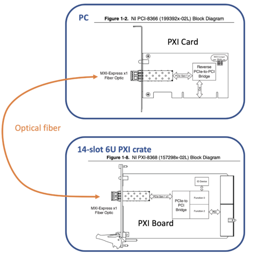
In order to control the Pixie16 digitizer, the DAQ computer needs to recognize the digitizer via a PCIe card( for example NI PCI-8366).
The digitizer crate (XIA PXI CompactPCI) has 14-slot. The 1st slot must be the communication card (for example, NI PXI-8366). The remaining 13 slots can be used for digitizer and other modules.
The PCIe card and PXI Board requires no driver. The DAQ computer will treat it as a bridge.
In the computer (LINUX), using the command lspci to show the PCI connection
>lspci
as an example, part of the output:
04:00.0 PCI bridge: Intel Corporation 41210 [Lanai] Serial to Parallel PCI Bridge (A-Segment Bridge) (rev 09)
04:00.2 PCI bridge: Intel Corporation 41210 [Lanai] Serial to Parallel PCI Bridge (B-Segment Bridge) (rev 09)
05:0f.0 Unassigned class [ff00]: National Instruments PXI-8368
06:05.0 PCI bridge: Texas Instruments PCI2050 PCI-to-PCI Bridge (rev 02)
06:0f.0 Bridge: PLX Technology, Inc. PCI9054 32-bit 33MHz PCI <-> IOBus Bridge (rev 0b)
In the above output, the NI PXI-8368 board on the crate is detected. Also the PCI9054 communication chip is detected.
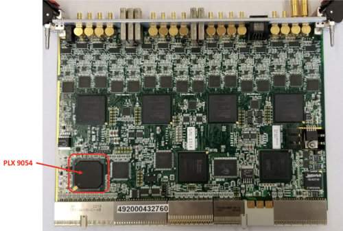
The PCI9054 (or PLX9054) chip is located at the corner of the Pixie16 digitizer.
The PCI9054 chip requires a driver. The driver is provided by Broadcom, and the package is called PlxSDK.
After the driver for the PCI9054 chip is done, the DAQ PC can talk to the digitizer. Next, the PixieSDK has to be installed for controlling the digitizer. The PixieSDK provides methods to control the digitizer.
Versions of Pixie16 Digitizer
In FSU, we have 100MHz (sampling rate) models and 250 MHz models.
500 MHz models are also used in Clarion2.
Each model has 16 channels. Using connector ?? </red>
Pixie16 firmware
The firmware can be downloaded from http://download.xia.com/#products/pixie16/firmware/
Data Structure
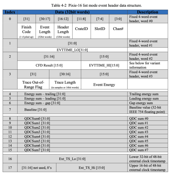
The recorded data is stored in the extern FIFO (first-in first-out) memory or ExtFIFO on the digitizer. A block of Data is formed by word, each word is 32 bit long. A minimum data block contains 4 words. When extra information is switched on, they will be stored afterward. The total length of a data block is called event length.
The data structure shown below and taken from the XIA Pixie-16 User Manual version 3.06 (a copy of the Manual), page 72.
The trace (if enabled) is stored after the header.
The data usually saved in a binary format. The evtReader from XIAEventBuilder package can read the binary format in root or in C++.
Incomplete data block when retrieving
It is possible that an incomplete data block may be retrieved at the beginning or at the end of ExtFIFO.
If the data is saved continuously, that will be not a problem.
Reading data
Timothy Gray developed code https://github.com/belmakier/libpixie.
XIAEventReader
XIA Event Reader is a command line-based data analysis program developed by Ryan Tang from FSU.
The program can be downloaded from https://github.com/goluckyryan/XIAEventBuilder
evtReader Class
A very useful code is the evtReader.h
This define the evtReader Class and can be loaded with root.
~>root -e '.L evtReader.h'
root$evtReader * evt = new evtReader("data_file")
root$evt->ReadBlock();evt->data->Print()
root$evt->ScanNumberOfBlock()
Broadcom PlxSDK
The chip was a product of PLX Technology, acquired by Broadcom Inc in 2014. The chipset driver is now called the Broadcom PCI/PCIe Software Development Kits . The package provides complete documentation and driver. The last release is on 2020.
Because of that, it only support Linux kernel around that time. I tested on
| OS | Status |
| Debian 10 | OK |
| Debian 11 | Error |
| Ubuntu 20 | Error |
Installation
After downloaded the package (here is a backup copy), unzip it, and we have
├── Documentation
│   ├── PLX API DLL with Visual Basic.htm
│   ├── PLX_LegacyAPI.pdf
│   ├── PlxRdkReferenceGuide.htm
│   ├── PLX_SDK_General_FAQ.pdf
│   ├── PLX_SDK_Linux_Release_Notes.htm
│   ├── PLX_SDK_Release_Notes.htm
│   └── PlxSdkUserManual.pdf
└── PlxSdk.tar
The tarball contains the driver. I extract the tarball into /usr/opt/PlxSdk. To setup the package (make) and also make the driver:
~>cd /usr/opt/PlxSdk/
PlxSdk>export PLX_SDK_DIR=$(pwd)
PlxSdk>sudo make                   # This shold make everything, including things in Samples
PlxSdk>cd Driver
PlxSdk/Driver>export PLX_CHIP=9054
PlxSdk/Driver>sudo ./builddriver 9054
PlxSdk>cd ../Bin
PlxSdk/Bin>sudo ./Plx_load 9054
Install: Plx9054
  Load module......... Ok (/usr/opt/PlxSdk/Driver/Source.Plx9000/Output)
  Verify load......... Ok
  Get major number.... Ok (MajorID = 243)
  Create node path.... Ok (/dev/plx)
  Create nodes........ Ok (/dev/plx/Plx9054)
In the last step, it loads the 9054 driver to the Linux Kernel. Fro more detail, see | elog
We can use lsmod to check the driver is loaded.
~>lsmod | grep "Plx9054"
Load 9054 driver on start up
To make the driver get loaded on start up, create a file at /etc/systemd/system/, say broadcom.service
[Unit]
Description=Broadcom PCI/PCIe 9054 Driver
After=network.target

[Service]
Type=oneshot
Environment=PLX_SDK_DIR=/usr/opt/PlxSdk/
ExecStart=/bin/bash /usr/opt/PlxSdk/Bin/Plx_load 9054
ExecStop=/bin/bash /usr/opt/PlxSdk/Bin/Plx_unload 9054
RemainAfterExit=yes

[Install]
WantedBy=multi-user.target
and then
sudo systemctl daemon-reload
sudo systemctl enable broadcom.service
Pixie SDK
PixieSDK provides all methods to control the digitizer, from parameters setting, writing/reading control register, starting and stopping the DAQ, to retrieving recorded data from its Extern FIFO (first-in-first-out) memory.
The SDK can be downloaded from GitHub in here.
The methods are listed in this web page.
PixieSDK 3.2
PixieSDK 3.3
PixieSDK 3.3 is similar to 3.2.
A copy of the programmer's manual is here
Legacy PixieSDK
DAQ Programs
NSCL DAQ (DDAS)
Pixie16 digitizer is supported by NSCL DAQ via the DDAS (digital data acquistion system) package.
In here, we are using the Singularity container method. To setup the NSCL DAQ, please check NSCL DAQ. After the setup, we assume the file structure is
| Path | function |
|---|---|
| /usr/opt/nscl-buster.img | Singularity container image |
| /usr/opt/opt-buster/ | NSCL DAQ pre-compiled files |
Load the PLX 9054 driver
In order to let the singularity recognize the PLX driver. We have to UNLOAD the Broadcom Driver v8.0 from above, and LOAD the driver in /usr/opt/opt-buster/plx.
To unload the 9054 Driver
/usr/opt/PlxSDK/Bin>sudo ./Plx_unload 9054
Compilation of the driver in the singularity shell
export env variable
Singularity nscl-buster.img:/usr/opt/plx>export PLX_SDK_DIR=$(pwd)
create Driver-<kernal> directory
Singularity nscl-buster.img:/usr/opt/plx>./mkdrivertree
compile the driver
Singularity nscl-buster.img:/usr/opt/plx/Driver-4.19.0-20-amd64>./builddriver 9054
 Build: Plx9054

 - PLA: Linux ver ??
 - KER: ver 4.19.0-20-amd64
 - INC: /lib/modules/4.19.0-20-amd64/build/include
 - CPU: x86_64 (64-bit Little Endian)
 - CMP: gcc
 - TYP: Driver
 - PLX: 9054
 - CFG: Release

 make[1]: Entering directory '/usr/src/linux-headers-4.19.0-20-amd64'
   CC [M]  /usr/opt/plx/Driver-4.19.0-20-amd64/Source.Plx9000/ApiFunc.o
   CC [M]  /usr/opt/plx/Driver-4.19.0-20-amd64/Source.Plx9000/Dispatch.o
   CC [M]  /usr/opt/plx/Driver-4.19.0-20-amd64/Source.Plx9000/Driver.o
   CC [M]  /usr/opt/plx/Driver-4.19.0-20-amd64/Source.Plx9000/Eep_9000.o
   CC [M]  /usr/opt/plx/Driver-4.19.0-20-amd64/Source.Plx9000/ModuleVersion.o
   CC [M]  /usr/opt/plx/Driver-4.19.0-20-amd64/Source.Plx9000/PciFunc.o
   CC [M]  /usr/opt/plx/Driver-4.19.0-20-amd64/Source.Plx9000/SuppFunc.o
   CC [M]  /usr/opt/plx/Driver-4.19.0-20-amd64/Source.Plx9000/Chip/9054/PlxChipApi.o
   CC [M]  /usr/opt/plx/Driver-4.19.0-20-amd64/Source.Plx9000/Chip/9054/PlxChipFn.o
   CC [M]  /usr/opt/plx/Driver-4.19.0-20-amd64/Source.Plx9000/Chip/9054/PlxInterrupt.o
   LD [M]  /usr/opt/plx/Driver-4.19.0-20-amd64/Plx9054.o
   Building modules, stage 2.
   MODPOST 1 modules
   CC      /usr/opt/plx/Driver-4.19.0-20-amd64/Plx9054.mod.o
   LD [M]  /usr/opt/plx/Driver-4.19.0-20-amd64/Plx9054.ko
 make[1]: Leaving directory '/usr/src/linux-headers-4.19.0-20-amd64'

 Driver "Source.Plx9000/Output/Plx9054.ko" built sucessfully
Load the driver in the host system
In the host system, due to the file structure, we need to create a symbolic link
/usr/opt>ln -s opt-buster/plx
go to the plx
/usr/opt>cd opt-buster/plx/Bin
/usr/opt/opt-buster/plx/Bin>sudo ./Plx_load 9054

Install: Plx9054
  Load module......... Ok (Plx9054.ko)
  Verify load......... Ok
  Get major number.... Ok (MajorID = 243)
  Create node path.... Ok (/dev/plx)
  Create nodes........ Ok (/dev/plx/Plx9054)
~>sudo lspci -vvv

06:0f.0 Bridge: PLX Technology, Inc. PCI9054 32-bit 33MHz PCI <-> IOBus Bridge (rev 0b)
	Subsystem: PLX Technology, Inc. PCI9054 32-bit 33MHz PCI <-> IOBus Bridge
	Control: I/O- Mem+ BusMaster+ SpecCycle- MemWINV- VGASnoop- ParErr- Stepping- SERR- FastB2B- DisINTx-
	Status: Cap+ 66MHz- UDF- FastB2B+ ParErr- DEVSEL=medium >TAbort- <TAbort- <MAbort- >SERR- <PERR- INTx-
	Latency: 32, Cache Line Size: 64 bytes
	Interrupt: pin A routed to IRQ 18
	Region 0: Memory at f7100000 (32-bit, non-prefetchable) [size=256]
	Region 2: Memory at f6800000 (32-bit, non-prefetchable) [size=8M]
	Region 3: Memory at f7000000 (32-bit, non-prefetchable) [size=1M]
	Capabilities: [40] Power Management version 1
		Flags: PMEClk- DSI- D1- D2- AuxCurrent=0mA PME(D0-,D1-,D2-,D3hot-,D3cold-)
		Status: D0 NoSoftRst- PME-Enable- DSel=0 DScale=0 PME-
	Capabilities: [48] CompactPCI hot-swap <?>
	Capabilities: [4c] Vital Product Data
pcilib: sysfs_read_vpd: read failed: Input/output error
		Not readable
	Kernel driver in use: Plx9054
With this, in the singularity shell, the PLX9054 driver is OK. To test, we use the NSCOPE to check
NSCOPE
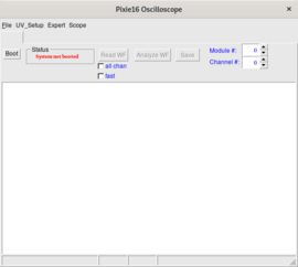
nscope is a GUI program for setting digitizer parameters, developed by Jeromy Tompkins (modified by David Caussyn). The program used the PLX Driver 7.0, Legacy PixieSDK, CERN ROOT 5.
In the /usr/opt/opt-buster/ddas/5.0-004/bin, there is a nscope.
In order to run nscope, we need other setting files
| file | function |
|---|---|
| cfgPixie16.txt | setting |
| pxisys.ini | required by Legacy PixieSDK, no need to change |
| XXXX.set | parameters setting file |
Those files can be copied from /usr/opt/opt-buster/ddas/5.0-004/share/readout/crate_1.
I created /home/ryan/readout to store those files.
cfgPixie16.txt
We have only 1 crate and 1 digitizer at slot 2.
1  #crateID
1  #number of modules
2  #slot for mod 0
/home/ryan/readout/create_1.set
How to set firmware location?
Run NSCOPE
run in Singularity shell
Singularity:~/readout>/usr/opt/ddas/5.0-004/bin/nscope
current working directory /home/ryan/readout
A window will pop out.
click the Boot, in the terminal, we have
------------------------
Initializing PXI access...
System initialized successfully.
Found Pixie-16 module #0, Rev=15, S/N=1314, Bits=16, MSPS=250

Booting Pixie-16 module #0
	ComFPGAConfigFile:  /usr/opt/ddas/firmware/2.1-000/firmware/syspixie16_current_16b250m.bin
	SPFPGAConfigFile:   /usr/opt/ddas/firmware/2.1-000/firmware/fippixie16_current_16b250m.bin
	DSPCodeFile:        /usr/opt/ddas/firmware/2.1-000/dsp/Pixie16_current_16b250m.ldr
	DSPVarFile:         /usr/opt/ddas/firmware/2.1-000/dsp/Pixie16_current_16b250m.var
	DSPParFile:         /home/ryan/readout/crate_1.set
--------------------------------------------------------

Start to boot Communication FPGA in module 0
Start to boot signal processing FPGA in module 0
Start to boot DSP in module 0
All modules ok
It correctly recognize the model, and load the corresponding firmware.
Taking Data
Make sure
- the DaqPortManager and RingMaster are running.
- the NSCOPE can run.
- the parameters is adjusted for trigger (using NSCOPE).
In this section, we need 3 terminals
- for checking the ringbuff
- for running the DDASReadout
- for running the dumper
Check the RingMaster statue
Singularity-00:~>/usr/opt/daq/11.4-013/bin/ringbuffer status
+----+------------+-------+-------------+--------+---------+---------+------+-------------+
|Name|data-size(k)|free(k)|max_consumers|producer|maxget(k)|minget(k)|client|clientdata(k)|
+----+------------+-------+-------------+--------+---------+---------+------+-------------+
|ryan|8194        |8194   |100          |-1      |0        |0        |-     |-            |
+----+------------+-------+-------------+--------+---------+---------+------+-------------+
The default name of a ring is the user name (so ryan). There is no process as producer and client, as no process is producing data (producer), and no process is getting the data from the ring buffer (client).
producer : DDASReadout
To run a (data) producer or the DDASReadout, in a new terminal, we run another singularity shell
Singularity-01:~/readout>/usr/opt/daq/11.4-013/bin/DDASReadout
The new event buffer size will be: 16934
Using a FIFO threshold of 10240 words
Trying to initialize pixie16
Crate number 1: 1 modules, in slots:2 DSPParFile: /home/ryan/readout/crate_1.set
Module event lengths: 4
------------------------
Initializing PXI access...
System initialized successfully.
Found Pixie-16 module #0, Rev=15, S/N=1314, Bits=16, MSPS=250

Booting Pixie-16 module #0
	ComFPGAConfigFile:  /usr/opt/ddas/firmware/2.1-000/firmware/syspixie16_current_16b250m.bin
	SPFPGAConfigFile:   /usr/opt/ddas/firmware/2.1-000/firmware/fippixie16_current_16b250m.bin
	DSPCodeFile:        /usr/opt/ddas/firmware/2.1-000/dsp/Pixie16_current_16b250m.ldr
	DSPVarFile:         /usr/opt/ddas/firmware/2.1-000/dsp/Pixie16_current_16b250m.var
	DSPParFile:         /home/ryan/readout/crate_1.set
--------------------------------------------------------

Start to boot Communication FPGA in module 0
Start to boot signal processing FPGA in module 0
Start to boot DSP in module 0
All modules ok
Module #0 : module id word=0xf1000fa, clock calibration=8
Resetting last channel timestamps on module: 0
Reader created
setup scalers for 1 modules
Scalers know crate ID = 1
%៛   <=== prompt for enter command to control the readout
It will leave us in the prompt.
client : dumper
We also need a (data) client to get the data from the ring buffer.
In a new terminal, open another Singularity shell, run the dumper program.
Singularity-02:~/readout>/usr/opt/daq/11.4-013/bin/dumper --count=50
If we go to the 1st terminal and check the ringbuffer
Singularity-00:~> /usr/opt/daq/11.4-013/bin/ringbuffer status
+----+------------+-------+-------------+--------+---------+---------+------+-------------+
|Name|data-size(k)|free(k)|max_consumers|producer|maxget(k)|minget(k)|client|clientdata(k)|
+----+------------+-------+-------------+--------+---------+---------+------+-------------+
|ryan|8194        |8194   |100          |482     |0        |0        |-     |-            |
|-   |-           |-      |-            |-       |-        |-        |584   |0            |
+----+------------+-------+-------------+--------+---------+---------+------+-------------+
We can see that the producer (ID 482) and client (ID 584) are there, and we are ready to take data.
Start and Stop
At the DDASReadout terminal, there are 3 commands:
| command | ||
|---|---|---|
| to start data taking | begin | the dumper terminal will show a lot of binary data stream. |
| to stop data taking | end | |
| to exit the DDASReadout | exit |
the data
The dumper program will store data to lmdata_mod0.bin, which is Pixie data format.
ReadOutShell
We are still using the Singularity-container method in here. The files are located in
| host system | Singularity | |
|---|---|---|
| NSCL DAQ | /usr/opt/opt-buster | /usr/opt/ |
The ReadoutShell is located at
Singularity>/usr/opt/daq/11.4-013/bin/ReadoutShell
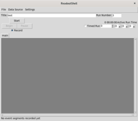
The ReadOutShell will load the ReadOutGUI. See the right picture.
SSH Pipe for Data Source
On the manual bar of the ReadoutGUI, Data Source >> Add.., Select SSHPipe.
| Host name : | localhost |
| Readout program : | /usr/opt/nscldaq/11.4-013/bin/DDASReadout |
| Working directory : | Click the Same as Readout |
| Command line options : | --ring=ryan --sourceid = 0 |
Since we are using ryan ring. See Pixie16_digitizer#Taking_Data hee.
To check, Data Source >> List, you should see the setting.
Since we are using ssh to connect the data source, even it is localhost, it will ask you password. So, better use command
~>ssh-copy-id localhost
To copy the ssh key. To create an ssh key if you don't have one, please see [Place holder]
A problem for ssh pipe with Singularity container is that, after ssh, it will not run Singularity shell but normal bash shell. To tackle this, two things must be done
export export SING_IMAGE=/usr/opt/nscl-buster.img
echo /usr/opt/opt-buster/:/usr/opt > ~/.singularity_bindpoints
The SING_IMAGE and ~/.singularity_bindpoints are recognized by the SSHPipe, so that it will go to Singularity constainer.
#!/bin/bash
export VERSION=11.4-013
export USROPT=/usr/opt/opt-buster/
export SINGULARITY_CONTAINER=/usr/opt/nscl-buster.img
export DAQPORTMANAGER=/usr/opt/daq/${VERSION}/bin/DaqPortManager
export DAQPORTMANAGERLOGFILE=$HOME/nscl_daq.log
export DAQPORTMANAGERPIDFILE=$HOME/nscl_daq.pid
export RINGMASTER=/usr/opt/daq/${VERSION}/bin/RingMaster
export RINGMASTERLOGFILE=$HOME/nscl_ring.log
export READOUT=/usr/opt/daq/${VERSION}/bin/ReadoutShell

## these two lins are important for ReadOut ssh know to use singularity
export SING_IMAGE=$SINGULARITY_CONTAINER
echo $USROPT:/usr/opt > ~/.singularity_bindpoints

singularity exec --shell /bin/bash --bind ${USROPT}:/usr/opt/ ${SINGULARITY_CONTAINER} ${READOUT}
Start & Begin
- To boot the Pixie16, or run DDASReadout, click the Start button.
- To Run, click the Begin button
To set the run name, Settings >> Event Recording.... You can set the Run file prefix.
The data will be stored at the Stagearea.
used in Clerion2
A special terminal-based DAQ program used in Clarion2 are developed by Jame M. Allmond and Tim Gray from ORNL.
PixieDAQ
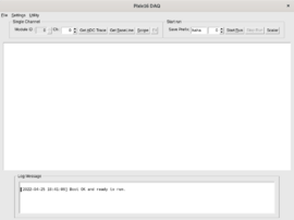
PixieDAQ is a GUI program for completely controlling and taking data from Pixie16 digitizer, developed by Ryan Tang. The program used the Boardcom PlxSDK 8.0, PixieSDK 3.3 and ROOT 6.24.
I assume the Boardcom PlxSDK, PixieSDK 3.3 are located at
| Boardcom PlxSDK 8.0 | : /usr/opt/PlxSdk |
| PixieSDK 3.3 | : /usr/opt/xia/PixieSDK |
The program can be downloaded at https://github.com/goluckyryan/Pixie16_GUI_DAQ. Its target platform is Debian 10, using CERN ROOT 6.24.06. Once downloaded the program. Unless the PlxSDK and PixieSDK are in different locations, using make should be able to compile the program.
There is only 1 configuration file Pixie16.conf
PixieDAQ will boot the digitizer when start.
To run,
~/pixieDAQ>./pixieDAQ
A window will pop-out.
Welcome to pixie16 DQ
Removing Pixie16Msg.log
======= check PLX PCI 9054 ...
Found PLX PCI 9054 driver.
Found PLX PCI 9054 card.
PLX PCI 9054 card does not detected problem.
======= Loading Configuration file : Pixie16.config
##########################
Number of Module : 1
 Slot Map :  2
Module ID :  0
--- configuration files for module-00 (slot-02)
  ComFPGA : ./firmware/pixie16_revf_general_16b250m_35921_2017-01-09/firmware/syspixie16_revfgeneral_adc250mhz_r33339.bin
   SPFPGA : ./firmware/pixie16_revf_general_16b250m_35921_2017-01-09/firmware/fippixie16_revfgeneral_16b250m_r36563.bin
 DSP Code : ./firmware/pixie16_revf_general_16b250m_35921_2017-01-09/dsp/Pixie16DSP_revfgeneral_16b250m_r35921.ldr
 DSP Var  : ./firmware/pixie16_revf_general_16b250m_35921_2017-01-09/dsp/Pixie16DSP_revfgeneral_16b250m_r35921.var
 DSP Par  : test_ryan.set
======= Booting Pixie16 System ...
Init Ok
Booting module ...
------------ Module-0
         Revision : 15
       Serial Num : 1314
         ADC Bits : 16
ADC sampling rate : 250
       # channels : 16
Boot Ok
Pixie16.conf
###########################################
## Pixie16 Configuration File:           ##
###########################################

### only for 1 crate for the moment

#Slot Number for Each Module
#This must start at 2 and proceed sequentially at the moment
#  slot modID fpgaID
S   2    0      25
#S   3    1      25

##########################################################################################################
## FPGA Files ID                                                                                        ##
## F Y X File, where Y = fpgaID < 100                                                                   ##
##                   X = 0 (sys*.bin), 1 (fip*.bin), 2 (DSP*.ldr), 3 (DSP*.var),  4(*.set)              ##
## Use this to save various FPGA files or to use a mixed board system                                   ##
##########################################################################################################

#250MHz 16-bit
F       25       0       ./firmware/pixie16_revf_general_16b250m_35921_2017-01-09/firmware/syspixie16_revfgeneral_adc250mhz_r33339.bin
F       25       1       ./firmware/pixie16_revf_general_16b250m_35921_2017-01-09/firmware/fippixie16_revfgeneral_16b250m_r36563.bin
F       25       2       ./firmware/pixie16_revf_general_16b250m_35921_2017-01-09/dsp/Pixie16DSP_revfgeneral_16b250m_r35921.ldr
F       25       3       ./firmware/pixie16_revf_general_16b250m_35921_2017-01-09/dsp/Pixie16DSP_revfgeneral_16b250m_r35921.var
F       25       4       test_ryan.set
########################################################################################################################
#120 space buffer limit
########################################################################################################################
Contact
- Ryan Tang mailto:rtang@fsu.edu
