Tandem Beamline Isolation (Fast Valve) System
Introduction
The Tandem Beamline Isolation System, historically referred to as the Fast Valve System, is now a PLC controlled vacuum valve interlock system. It is designed to quickly respond to vacuum failures by isolating the accelerator beamline sections and preventing the failure from propagating further. This system also interlocks with the Pelletron to shut down operation when vacuum faults are detected in the vacuum proximal to the accelerator tubes. Each of the six valves controlled has a corresponding valve control panel (VCP) which allows the valve to be configured for operation and/or maintenance activities. All user operation occurs through these valve control panels.
Photos
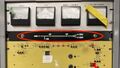
Master Control Panel
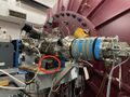
High Energy Valve Control Panel
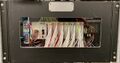
Control Room Valve Status Display Panel
Functional Block Diagram

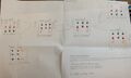
Rendered CAD graphic of VCP Front Panel


Operation
All operator actions are performed through the Valve Control Panels (VCPs). Refer to the VCP front panel graphic for reference while reading this section. There are no operator actions available at the Master Control Panel (MCP).
The valve control panel is always located near the associated valve. The front panel is divided into three sections; LEFT, MIDDLE, and RIGHT. Note the small vertical lines marking these divisions. You may think of the MIDDLE section as representing the valve itself, and the LEFT and RIGHT sections as representing the vacuum sensors on the corresponding side of the valve.
Sensor Indication and Control
Take a look at the left side of the VCP. At the top, there is a green lamp that reads GOOD. When lit, the pressure in the beamline is below, or better than, the set point threshold. Below that, there is a red lamp that reads BAD. When lit, the pressure in the beamline is above, or worse than, the set point threshold or the sensor is off or otherwise not functioning. The GOOD and BAD lamps should never be lit at the same time, with one exception covered later. The lowest indicator on the LEFT side is colored yellow and reads IGNORE. This is both a lamp AND a momentary contact switch. This switch is used for maintenance activities. Pressing this switch will cause the system to IGNORE the sensor on the corresponding side. While that sensor is being ignored, the yellow lamp will flash at a 1 second rate to remind operators that this sensor is being ignored. The RIGHT side lamps and switches function identically for the sensor on that side of the valve.
| On the VCP, LEFT and RIGHT refer to the sensor direction from the valve - as viewed from the front panel - and have NO RELATIONSHIP to the idea of upstream and downstream beam reference. |
While not immediately obvious, one should understand that the sensor that monitors that status of the vacuum in its section will display that status on 2 or 3 different valve control panels. This is because the sensor monitors the section between 2 or three valves. Correspondingly, toggling the IGNORE function on one VCP will result in the IGNORE function being displayed on 2 or three VCPs, depending on the ignored sensor position. The only exception to this are the sensor stations on either side of the tandem. This is because there are actually two separate sensors (as well as pump stacks) between the low and high energy valves.
Valve Indication and Control
Recall that the MIDDLE section of the VCP can be thought of as representing the valve. There are two combination lamp/switch assemblies. The green one is labeled OPEN/ACK while the RED one is labeled SHUT. When the valve is open, the top lamp will be lit GREEN, and when the valve is shut, the lower lamp will be lit RED.
If the valve is SHUT, and you wish to OPEN the valve, then one of two conditions must be met:
- The vacuum on both the LEFT and RIGHT must be good, with the GREEN lamp lit or,
- Any sensor that does not indicate a good vacuum must be in the IGNORE mode.
If the valve is OPEN, and you wish to SHUT the valve, simply press the switch marked SHUT. Shutting the valve is NEVER impeded for any reason.
Valve status is also duplicated on the Control Room Display Panel for operator convenience.
Fault Indication and Assessment
When a Tandem vacuum system fault occurs, one of the sensors will detect it and make a transition from GOOD to BAD. This transition is detected by the PLC, the offending sensor is recorded, and the system will enter fault mode. All of the beamline isolation valves will immediately shut, with the exception of the SNICS Source exit valve. This valve remains open to sustain pumping on the source inflector magnet section, unless the SNICS Source sensor originates the fault. In this case, the SNICS Source exit valve will shut also.
The Tandem operator must then survey each vacuum station and determine the cause of the fault. Once the cause of the fault is identified, corrected, and the vacuum status restored, the valves may be reopened. Other valves in the system, with good vacuum on each side may be opened at any time after the system trips, even if the failure has not been addressed yet.
Occasionally, a transient condition may generate a fault. This occurs when a vacuum sensor makes a GODD to BAD transition, which trips the system, but then transitions from BAD to GOOD before an operator can identify the cause. In order to support useful troubleshooting, the PLC is programmed to "remember" which station caused the fault. Should the offending sensor transition back to GOOD, the PLC will indicate that the vacuum is GOOD by lighting the green lamp, but will flash the red BAD lamp at a 0.5 sec rate to indicate which sensor caused the fault. When this occurs, before the valve can be opened, one must "acknowledge" the transient indicator by pressing the OPEN/ACK switch. This will stop the BAD lamp from flashing and reset the PLC transient tracking system. The valve may now be opened by the OPEN/ACK switch as usual.
Fault Integration with Tandem Pelletron
If the fault occurs in the Tandem's High Energy or Low Energy vacuum station, the Pelletron Interlock will trip. This is automatically re-enabled after 1 minute if the vacuum in both of these stations are restored. Vacuum faults in other stations will not trip the Pelletron. Note that the IGNORE toggle will not permit Pelletron operation. The vacuum sensor MUST indicate GOOD vacuum in order for the Pelletron interlock to be satisfied. Bypassing the sensor with a prepared shorting connector is possible for emergency operation, but provides no protection whatsoever and should only be done with laboratory management approval.
Technical Description and Troubleshooting
Unfinished...
This section is intended for those who need to troubleshoot, modify, or repair the system.
Basic Hardware
The Tandem Beamline Isolation (Fast Valve) System uses a programmable logic controller (PLC) to perform command and control of the entire system. All inputs to and outputs from the PLC are digital I/O (DIO) signals using 24VDC logic levels. The PLC takes inputs from the vacuum sensors and from switches in the Valve Control Panels (VCPs) and provides outputs to the VCPs and the control room Valve Status Panel.
PLC
The PLC used is the CLICK Model # C0-01DD1-D from Automation Direct. Power for the PLC and it's associated DIO modules is supplied by a CLICK power supply, Model # CO-01AC power supply. This power supply only supplies power for the internal logic operation of these modules. Power for all external devices, such as the VCP lights, switches, relays, etc., is supplied by a second 24 VDC power supply, Model # PSB24-060-P, originally available from Automation Direct. The PLC, DIO moudles, and both power supplies are DIN rail mounted in the Master Control Panel (MCP).
As of this writing (05 Dec 2025) The PLC is still listed for sale at $153.00, the Click power supply at $73, and the auxiliary power supply (PSB24-060-P) has been retired, with the Model # PSB24-060S-P listed as the replacement at $55.00
Currently, the critical spares inventory contains the following items related to the MCP:
- CLICK PLC, Model # C0-01DD1-D, preprogrammed w/ software version 2, release 1, Quantity 1 used, Quantity 1 spare
- CLICK Power Supply, Model # CO-01AC, Quantity 1 used, Quantity 1 spare
- CLICK Digital Input Module, Model # C0-16TD1, Quantity 3 used, Quantity 1 spare
- CLICK Digital Output Module, Model # C0-16ND3, Quantity 3 used, Quantity 1 spare
- Power Supply, Model # PSB24-060-P, Quantity 1 used, Quantity 2 spare
- Relay, Model # QM2X1-D24, Quantity 1 used, Quantity 2 spare.
| As of this writing (05 Dec 2025), the QM2X1-D24 Relay had been DISCONTINUED, WITHOUT REPLACEMENT. The MCP uses one of these relays for the PELOTRON interface and each VCP uses one of these relays for valve control. |
PLC Programming
Programming of the CLICK PLC is accomplished using freely available software from Automation Direct. The PLC is programmed using ladder logic w/ a few advanced features such as timers, clocks, etc. The program is heavily commented in the hope that whoever follows will understand it with as little difficulty as possible. A PDF version of the program can be accessed at the following link:
Media:FV INTLK TANDEM Ver 3r0 26feb26.pdf
The wiki does not permit my uploading the click data file. I'll consult for other possibilities and note them here.
VCP
There is a Valve Control Panel (VCP) associated with each valve. The VCP interfaces directly with the MCP and the valve directly. All VCPs are identical and can be interchanged. The logic associated with the directionality of the sensors is actually accomplished via the wiring between the VCP and the MCP and can not be changed easily. This is why some VCPs will have the upstream sensor on the left, while other VCPs will have the upstream sensor on the right. Re-orientation of the VCP's face direction cannot be done w/o changing the wiring of the system.
The VCP uses indicators and combination switch/indicators manufactured by IDEC. An Automation Direct QM2X1-D24 relay is used for energizing the gate valve solenoid valve. Back panel connectors are Molex, and the entire assembly is housed in a Hammond 513-0900 aluminum box.
Note to self: Include the VCP bill of materials here somewhere.