He refrigerator: Difference between revisions
| Line 29: | Line 29: | ||
See section 2.1.14 on the [[:File:He refrigerator Operator manual.pdf|Operator manual]]. | See section 2.1.14 on the [[:File:He refrigerator Operator manual.pdf|Operator manual]]. | ||
[[:File:Directsoft 405 PLC manual.pdf]] | The manual of the DL-405 CPU is [[:File:Directsoft 405 PLC manual.pdf | here]]. | ||
== | The PLC program is [[File:PLC program for the DL-405 CPU.zip | here]]. | ||
== Instructuion to clear and load the PLC program == | |||
This procedure is done using DirectSoft 6. | |||
[[File:Directsoft 6 clear and upload PLC program.png|800px|frameless|none|Screenshot of DirectSoft 6]] | |||
To clean up the PLC program in the CPU, use the "Clear PLC" at the 3rd row, choose "Select ALL". | |||
To upload a PLC program in the CPU, there is 2 buttons to click. | |||
# click the "Disk to PLC" at the 3rd row, choose "Select ALL". | |||
# click the "Write PLC" at the 2nd row. | |||
= Temperature sensors = | = Temperature sensors = | ||
Revision as of 17:05, 2 September 2022
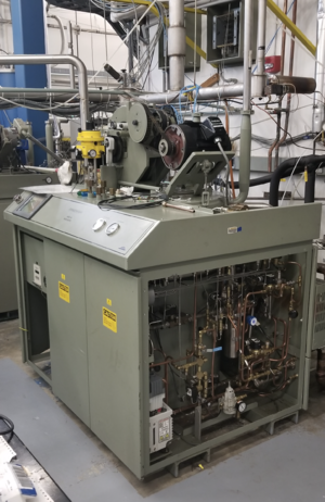
The He refrigerator, or liquefied, Model 1630S from the Cryogenic Plants and Services, Linde BOC Procee Plants LLC. This model operates on an analog system and has been upgraded so that a computer can control it.
The model is used to produce liquid He as a close cycle 4.6 K refrigerator. It has a purification system for recycling the air-contaminated He gas.
He refrigerator Operator manual
| 1 bar = 14.5038 psi |
Operation principle
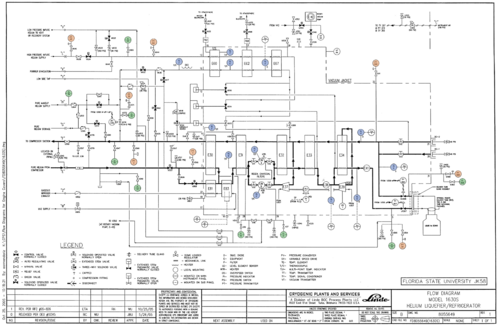
The main flow of the He gas is shown in the right diagram. The room temperature He gas (~17.2 bar) from a compressor started from the left. It passes through the main heat exchanger (E30, E31, E32, E33, and E34) to cool it down. A precooler heat exchanger (E81) and boiler heat exchanger (E83) can be used with liquid nitrogen. The liquid nitrogen first flow to the boiler and then the precooler. The He gas can be purified using the expansion engine charcoal absorbers (E36A, E36B, E38), up to 10% air impurity.
After the absorber, part of the He gas flows through the No. 1 expansion engine (E37) and is cooled by isentropic expansion, where the entropy remains unchanged, then flows to the low-pressure return stream at near atmospheric pressure (1.01325 bar). The other part of the He gas, still at high pressure, flows to E32 and E33, and enters another charcoal absorber (E38) to purify the gas. And then the He gas splits into 2 parts, one part enters the No. 2 expansion engine (E39) using the isentropic expansion to lower the temperature and send it to the low-pressure return stream for cooling the other part of the He gas. After past through the final heat exchanger (E34), the He gas is throttled to nearly atmospheric pressure and partially liquified using the Joule-Thomson valve (JT-V307) using adiabatic expansion. The low-pressure liquid/gas mixture goes to the dewar, the liquid is stored while the gas will go to the return stream.
The No. 1 expansion engine (E37) normal inlet temperature is less than 80 K. No. 2 expansion engine's inlet temperature is less than 20 K.
The return He gas, which is still cold enough, also flows through the main heat exchanger to provide cooling for the room temperature He gas. After that, the return He gas will go back to the He compressor at the end.
A detailed operation can be found in section 2 of the operation manual.
Programmable Logic Controller
See section 2.1.14 on the Operator manual.
The manual of the DL-405 CPU is here.
The PLC program is File:PLC program for the DL-405 CPU.zip.
Instructuion to clear and load the PLC program
This procedure is done using DirectSoft 6.
To clean up the PLC program in the CPU, use the "Clear PLC" at the 3rd row, choose "Select ALL".
To upload a PLC program in the CPU, there is 2 buttons to click.
- click the "Disk to PLC" at the 3rd row, choose "Select ALL".
- click the "Write PLC" at the 2nd row.
Temperature sensors
There are 4 thermal diodes for liquid He, and 5 thermal couples. The thermal diodes are read by a device, and the thermal couples are connected to PLC. A CoProcessor is used to read the thermal diodes reading via the device.
Thermal diodes --> a device --> (RS232/422/485) --> CoProcessor --> (PLC backplane) --> CPU
Thermal couples --> PLC --> (PLC backplane) --> CPU
CoProcessor
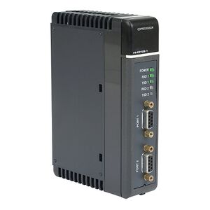
The F4-CP128-1 CoProcessor is used. It has 2 ports. Port-1 is connected to a PC for control and programming. Port-2 is used to read the temperature from the thermal diodes. Two references can be found Tech-sheet and manual.
The ABM Commander (for windows) can be used to send commands to the CoProcessor.
The FACTS Extended BASIC is the language to control the CoProcessor.


