Ion Sources: Difference between revisions
| Line 11: | Line 11: | ||
== Tuning Beam out of the SNICS Source == | == Tuning Beam out of the SNICS Source == | ||
These instructions assume the correct cathode is installed and the necessary hardware/cable changes for selecting an ion source has been made. Also assumed is that the source has been turned down after a previous run but not necessarily to the idle mode. '''Do not inject more than 10 microamperes of beam into the accelerator under any circumstances.''' | These instructions assume the correct cathode is installed and the necessary hardware/cable changes for selecting an ion source has been made. Also assumed is that the source has been turned down after a previous run but not necessarily to the idle mode. <span style="color:#FF0000>'''Do not inject more than 10 microamperes of beam into the accelerator under any circumstances.'''</span> | ||
# Open the source exit valve in the Tandem Vault. | # Open the source exit valve in the Tandem Vault. | ||
# Insert the L.E. faraday cup and depress the corresponding push button on the integrator panel. Select the most sensitive scale on the integrator initially and then adjust the scale if and when the beam current pegs the meter. | # Insert the L.E. faraday cup and depress the corresponding push button on the integrator panel. Select the most sensitive scale on the integrator initially and then adjust the scale if and when the beam current pegs the meter. | ||
Revision as of 17:19, 8 April 2022
Sputter Source
Sputter Source is also called SNICS.
Operation
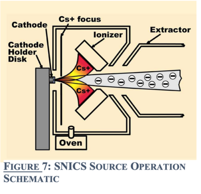
The Source of Negative Ions by Cesium Sputtering (SNICS) produces a negative ion beam. A reservoir of cesium metal is heated so that cesium vapor is formed. This cesium vapor comes from the cesium oven into an enclosed area between the cooled cathode and the heated ionizing surface. Some cesium condenses onto the cool surface of the cathode and some of the cesium is ionized by the hot surface. The positively charged ionized cesium accelerates towards the cathode, sputtering material from the cathode at impact. Some materials will preferentially sputter neutral or positive particles which pick up electrons as they pass through the condensed cesium layer on the surface of the cathode, producing the negatively charged beam.
Tuning Beam out of the SNICS Source
These instructions assume the correct cathode is installed and the necessary hardware/cable changes for selecting an ion source has been made. Also assumed is that the source has been turned down after a previous run but not necessarily to the idle mode. Do not inject more than 10 microamperes of beam into the accelerator under any circumstances.
- Open the source exit valve in the Tandem Vault.
- Insert the L.E. faraday cup and depress the corresponding push button on the integrator panel. Select the most sensitive scale on the integrator initially and then adjust the scale if and when the beam current pegs the meter.
- In the Control Room, turn the ion source deflectors to zero.
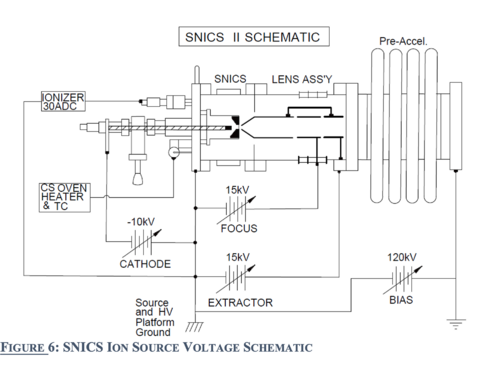
- heater current to increase the beam current; do not exceed 290 watts or premature failure of the heater will occur. If there is still insufficient beam current, increase the cesium boiler temperature in 100◦ steps separated by 45 minute intervals. Do not exceed 490◦ or the cesium vapor will cause internal arcing in the source. If there is too much beam, reduce the boiler temperature and monitor the beam current. If less beam is still desired reduce the Ionizer heater current in Turn on and bring up the Preaccelerator High Voltage Supply to 120 KV.
- Adjust the inflector magnet supply to indicate the predicted setting for the negative ion that is to be injected into the Tandem. A table is provided on the inflector control panel.
- If the beam has been run before and the source parameters are known, adjust the SNICS Cathode and Extractor supplies to those values at the High Voltage Cage out in the Tandem Vault. If the Ionizer heater is to be adjusted do it in 4 ampere steps separated by 4 minute intervals.
- If no parameters have been recorded or cannot be found set the SNICS Cathode and Extractor supplies to 7.5 KV.
- Beam should be present on the L.E. cup; if not, adjust the inflector magnet slightly and attempt to find and maximize beam current. The inflector magnet should not be more than 0.15 units off of the predicted setting.
- An iterative approach is used to maximize beam on the L.E. cup. After the magnet is fine tuned, adjust the SNICS Cathode and Extractor supplies in the Tandem Vault to maximize beam current. When satisfied, again adjust the inflector magnet in the Control Room and then the source H.V. supplies again. After this second round of tuning use the source deflectors in the Control Room to increase beam current on the L.E. cup. More rounds of adjustments should be attempted; however, maximum beam transmission through the Tandem does not occur at the same settings as those for maximum L.E. faraday cup beam current. Mostly the source deflectors and the inflector magnet require slight readjustment when tuning through the Tandem.
- Assuming all the focusing and deflector elements are maximized for beam current, one can only adjust the Ionizer heater and the boiler temperature to attain more beam form the source. First increase the Ionizer one ampere steps until the desired current is reached. The beam is ready for injection.
Should one not have success with tuning the desired beam, reducing the ion source deflectors to 50% of the optimum for a couple of iterations of source voltages and inflector magnet adjustments might be a useful approach. Ultimately, the deflectors should be adjusted to give the maximum beam on target.

