SF6 Gas Handling System
Worthington Compressor
The Worthington compressor was installed in the early ’70s. It is a two stage oiless compressor with teflon piston rings and metallic reed valve assemblies. In 1995 the Dresser Rand was the current spare parts supplier (tel.1-800-634-5565). The compressor model no. is 12 1/2 X 5 X 13 HB B-2 and the serial no. is L89186. The compressor is driven by a 125 HP 3-phase motor coupled by belt and pulley. The internal connecting rod and crank do require lubrication and the recommended lubricant is ISO-VG-150; AGMA Grade 4.
The compressor is cooled with well water which is circulated through the water jacket surrounding the compressor cylinders and the heat exchanger. If the well water supply should fail the supply automatically changes over to the city water supply. The discharge from the compressor is sent to the dump well unless a valve change is made to route the water to the storm drain. The two labeled valves in the Gas Handling Room near the compressor need to be changed to allow the rerouting. After conditions return to normal and the well supply becomes available again, changes should be made to reroute the well water from dumping down the storm drain; the aforementioned valves will need to be put back in the original state. The switch from city water to well water supply is again automatic.
Emergency Valve Closures
If during a gas transfer the compressor should stop, a seal fail or some type of major leak of SF6start, it is important to safeguard the gas inventory. Also, at any time should a SF6 loss due to a failure on the Tandem pressure vessel or the storage tank and any of the directly attached valves occur a transfer of the SF6 inventory is suggested immediately. This, however, should not take precedent over safety as large quantities of SF6 can displace life sustaining air. Depending on where one is in the gas transfer the compressor may or may not be running; the response depends on whether the compressor is running.
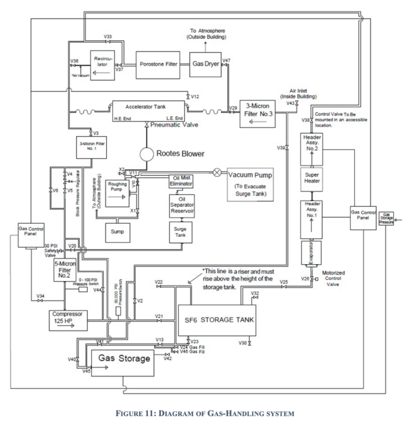
Below are the responses to three sets of circumstances that may confront the operator; some valves may or may not already be closed. The valves affected in the Gas Handling Rm. are shaded red in the preceding room layout (figure 5). After the crisis has passed and the transfer piping schematic (figure 11) is consulted a more sensible arrangement of valves may be preferred.
Compressor is Off: Large Leak Detected
Compressor Has Failed During Gas Transfer: No Leak Detected
Compressor Is On: Large Leak Detected
Equalizing the SF6 Gas to the Outside Storage Vessel
Time: ∼ 25 minutes. Change in Pressure: 80 to 50 lbs/in2. Ensure these valves are closed before beginning the gas transfer. Refer to the locator map (figure 5) for their approximate location: 38, 39, 43, 47, 35, 36, 4, 6, 13, 46, 40
- In the Control Room, turn off the power to the Terminal Potential Stabilizer panel and withdraw the Corona Probe.
- In the Tandem Vault, open the H.E. Tandem gas valve at the bottom of the North end of the tank. Ensure the tank lights are turned off.
- Open the L.E. Tandem gas ball valve at the bottom of the tank South end.
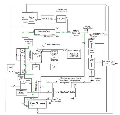
- Open valve 41, located at the south wall of the gas handling room, to allow the gas to equalize into the Storage Vessel.
- Open valve 29 to collect the gas left in the piping from last gas transfer. The valve will probably be open already. If gas is not heard flowing it may be that valve 3, on the East side of the Tandem is closed, open it.
- In the Control Room, remove the control power key and place it on top of the electronic rack.
- Switch the Gas Pressure Alarm panel to the mute mode.
- When gas is no longer heard flowing through the piping, go to the next step.

