Split-Pole Spectrograph: Difference between revisions
No edit summary |
No edit summary |
||
| Line 5: | Line 5: | ||
|} | |} | ||
The '''Enge Split-Pole Spectrograph''' <ref>H.A. Enge, NIM 162, '''161''' (1979) https://doi.org/10.1016/0029-554X(79)90711-0</ref> consists of a reaction chamber, a split-pole magnetic spectrograph, a position-sensitive ionization drift chamber, and a plastic scintillator. It has an angular acceptance of 128 msr (vertical ±40 mrad, horizontal ±80 mrad). The maximum B-field is 1.63 T with a radius of curvature from 511 mm to 920 mm. The mean radius is 600 mm. | The '''Enge Split-Pole Spectrograph''' <ref>H.A. Enge, NIM 162, '''161''' (1979) https://doi.org/10.1016/0029-554X(79)90711-0</ref> consists of a reaction chamber, a '''split-pole magnetic spectrograph''', a '''position-sensitive ionization drift chamber''', and a '''plastic scintillator'''. It has an angular acceptance of 128 msr (vertical ±40 mrad, horizontal ±80 mrad). The maximum B-field is 1.63 T with a radius of curvature from 511 mm to 920 mm. The mean radius is 600 mm. | ||
== History == | == History == | ||
Revision as of 20:02, 27 May 2023
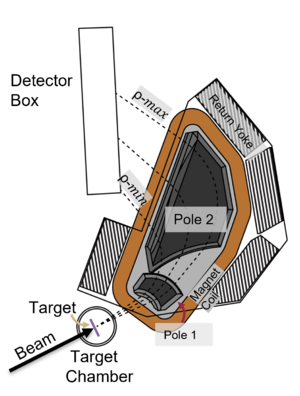 Annotated picture of the SE-SPS, An plain picture is here : File:SPS Magnet.png |
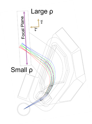 SE-SPS COSY simulation. An plain picture is here File:SPS Sketch With Cosy.png |
The Enge Split-Pole Spectrograph [1] consists of a reaction chamber, a split-pole magnetic spectrograph, a position-sensitive ionization drift chamber, and a plastic scintillator. It has an angular acceptance of 128 msr (vertical ±40 mrad, horizontal ±80 mrad). The maximum B-field is 1.63 T with a radius of curvature from 511 mm to 920 mm. The mean radius is 600 mm.
History
The SPS was at the Yale University. It was moved to FSU around 2013 (?).
Magnet
The SPS contains 2 dipole magnets: pole-1 and pole-2. The magnet can be rotated from 0 to 55 degrees in the lab. The magnetic field has an upper limit of 1.63 T (or 16.3 kG).
Focal plane detector
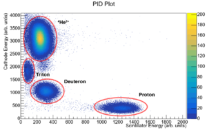
The focal plane detector consists of an ion chamber with a set of delay lines to detect the position of a particle along the focal plane and a plastic scintillator to detect the energy of the incoming particle. Using the energy loss of the particle through the ion chamber with the energy deposited in the scintillator, particles of different charges and masses can be identified.
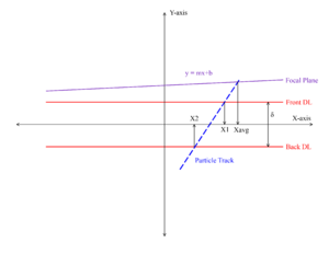
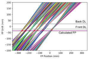
There are two position-sensitive delay lines in the focal plane detector. By reconstructing the particle trajectory using the position information of both delay lines, the resolution can be enhanced by correcting for the kinematic shift of the reaction.
SABRE
The Silicon Array for Branching Ratio Experiments
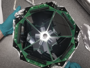
SABRE is a silicon array designed around branching ratio experiments with the SPS. SABRE sits at backwards angles from the target, and covers roughly 30% of 4pi. SABRE has both thick and thin dead-layer detectors, with the thin dead-layer detectors capable of reaching ~200 keV thresholds for protons and deuterons.
https://www.sciencedirect.com/science/article/pii/S0168900221002837
SPS Experiment Guide
Media:SPS_Experiment_Guide.pdf
SPS Operating Procedures
I created this section as a place to store procedures for the chamber swaps, however, I expect there are other things we might want to document here. -p
Repositories
Contact
- Jeff Blackmon mailto:blackmon@lsu.edu
- Ingo
- who should be contacted?
References
- ↑ H.A. Enge, NIM 162, 161 (1979) https://doi.org/10.1016/0029-554X(79)90711-0
